The ability to virtually validate a plastic part design has become an important tool for designers and manufacturers to develop quality new products while meeting the continually compressed time-to-market deadlines. The use of structural finite element analysis (FEA) early in the design stage allows an engineer to make intelligent decisions regarding nominal wall thickness, stiffening rib placement, and material selection. Additionally, the integration of many structural FEA packages into traditional CAD packages has exposed this tool to a much wider audience. However, to fully realize the potential of this powerful tool careful consideration of the inputs for the simulation need to be made (Remember Garbage In – Garbage Out). One important decision that needs to be made is if a non-linear analysis needs to be performed. Deciding to run a non-linear analysis can significantly increase the accuracy of a simulation, but often takes significantly more time for the computer to provide a solution. So when should an engineer perform a non-linear analysis?
Material Non-Linearity
When most engineers and designers learn about material behavior, they are taught that the stiffness of the material can be characterized by a single value – Young’s Modulus. The concept of Young’s Modulus is that the response of a material is proportional to the load. Under this assumption, if a cantilevered beam deflected 0.125″ when a 10 pound load is applied, then the beam would deflect 0.250″ if the load was increased to 20 pounds. While Young’s Modulus makes it easier to characterize the behavior of a material, it also over-simplifies it. In reality, all materials are inherently non-linear, as it is not possible to characterize a material by a single value for all load types and conditions. Young’s Modulus becomes particularly problematic when characterizing the behavior of polymers. In general, polymers only exhibit a very small linear region with most resins deviating from this behavior with strains less than 1%.
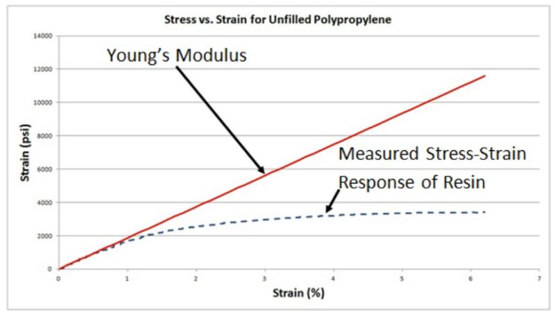
Figure 1: Characterizing the stiffness of a plastic resin by using Young’s Modulus (i.e. linear assumption) can lead to an over-prediction in stress and stiffness of the part.
The point at which the material behavior deviates from the linear behavior is referred to as the proportional limit. The danger with using Young’s Modulus beyond the proportional limit of the material is that the predicted stiffness of the designed part and the predicted stress in the part will be overpredicted (Figure 1). Over predicting these two design parameters can lead to over-designing the part and minimize the benefit of using plastics in the first place. To avoid this material characterization oversight, the designer and analyst should look at the stress-strain behavior of the polymer and determine if the Young’s Modulus accurately portrays the material response over the strain range of interest. If it is determined that Young’s Modulus does not accurately predict the behavior of the resin, then a more accurate model should be used. Many more refined models have been developed that better predict the behavior of polymers. Most commercial software even allows users to import stress-strain data into the program to account for any non-linearity.
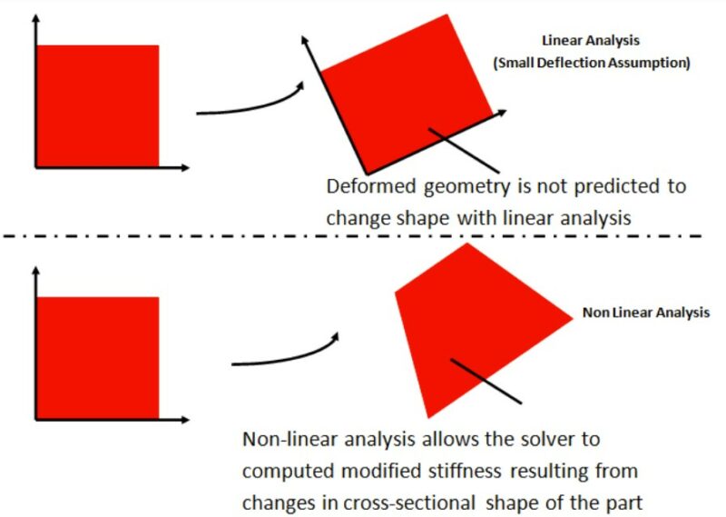
Figure 2: When parts experience large deflections and rotations, the cross-section of the geometry can change, which can alter the cross-section of the part. Only a nonlinear analysis can capture the geometry change of the part and resulting change in stiffness.
Geometric Non-Linearity
Another source of non-linearity is a result of changing geometric cross-sections as a result of the loading. Geometric non-linearity takes into account the fact that the geometry cross-section can change as a result of large deformations (i.e. large displacements, large rotations, large strains). A linear analysis assumes that the stiffness of a part stays constant regardless of deflection. If the deflections of the part remain small relative to the overall dimensions of the part, it is reasonable to assume that the change in the geometry has a relatively insignificant effect on the overall response of the part. However, as the deflection of the part increases, the resulting geometric change in the part can yield either a stiffer or more compliant structure (Figure 2). It is generally accepted that if the rotation of the part remains less than 10-15 degrees and the deflection of the part is significantly less than the overall dimensions of the part then a linear analysis will yield reliable results. However, if an initial linear analysis results in large deformations and rotations, then the analysis should be converted to non-linear to account for the modified stiffness of the part.
Boundary Non-Linearity (Contact)
Boundary non-linearity arises when the boundary conditions in a FEA model change during the analysis. It is particularly prevalent when modeling contact between mating components, or during impact simulations. When modeling contact between mating components, the solver has to constantly calculate and monitor how large of a contact area is generated with the applied loads. The contact area is calculated by determining how many nodes in each body are within a specified tolerance. If two nodes, on separate bodies, are within the prescribed tolerance the contact is considered closed, and a reaction force is applied to the nodes to prevent them from penetrating further through each other. If the nodes remain outside the specified tolerance, the contact is considered open and no reaction force is applied. As the contact area between the mating components changes, the force transfer between the two components changes, which alters the stress distribution at the interface. In a linear analysis, the solver assumes the contact surfaces remain constant, and does not perform this calculation.
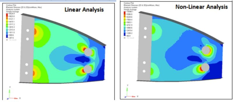
Figure 3: Not accounting for the boundary non-linearity and changing contact areas during an analysis can lead to errant predictions in the stress distributions throughout the part.
Figure 3 shows an example of a plate being held in position by two bolts. The image on top shows the results of a linear analysis, while the image on the bottom shows the results of a non-linear analysis. Comparing the images shows that the stress distributions and predicted magnitudes change between the two different solvers. The inability of the linear solver to allow the contact interfaces between the bolts and the plate to change as the load is applied results in significantly different stress distribution of the part and an underprediction of the stress level in the plate. Properly modeling this contact interface and identifying the high stress areas is important not only for evaluating the structural integrity of the part, but also to help avoid placing manufacturing defects such as weld lines in these high stress areas.
Structural finite element analysis is a very powerful tool that has opened the door for plastics in many different fields. The ability to validate a plastic part design and make critical decisions regarding the final design can save a significant amount of time and money. However, care needs to be taken to ensure the analysis is accurately modeling the physical system. Ensuring the non-linear effects of the plastic material, loading condition and boundary conditions are accounted for in a simulation will help designers and engineers make the correct decisions and allow them to bring their product to market faster.