Threads in plastic parts are commonly used to assemble or fasten components. The thread geometry used for plastic threads is commonly inherited from existing specifications used in metals. In many cases there is given little latitude to change the thread geometry since it must conform to an already existing mating component. In these instances, the designer may be limited to slight modifications of the geometry. However, a frequent problem with plastic threads is not always related to the thread geometry, but rather, the design of the whole component. After examining thousands of failures originating on threaded plastic components, this article captures a few often forgotten, but basic aspects of plastic thread design learned over the years.
Regardless of the thread standard used, an important design aspect is to avoid sharp edges, which create stress concentrations. A sharp geometrical transition is inherent to the root of the thread. Some standards allow rounding or truncating the thread root up to 1/8 of the thread pitch (Figure 1). For these, the thread root should be smoothly rounded to reduce the stress concentration. However, even after smoothing the thread root, a stress concentration will still exist. For this reason, proper part design should consider the whole component, not just the geometry of the thread. Factors such as wall thickness, geometry adjacent to the threads and material selection all play a crucial role. The role of wall thickness is more obvious because it directly affects the stress of the part, thus the stress at the thread root. Conversely, wall thickness has a less obvious effect on processing. Thickness variations within the component can produce molded-in stresses that could further aggravate the stress concentrating effect of the threads. Therefore, the designer must balance the unintended consequences resulting from a specific design selection.
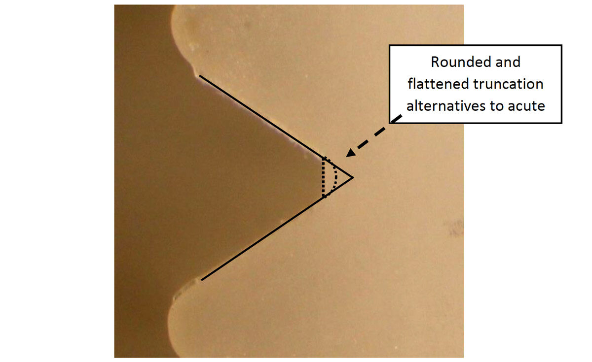
Figure 1. Rounding of thread root
Another important design parameter is the plastic material selected. Some plastics are more sensitive than others to cracking due to stress concentrations. The notch sensitivity is an important property affecting the performance of the threads. Additionally, the long-term and creep properties of the material are crucial. The stress concentration created by the edge at the thread root would accelerate creep and eventually fail. The designer can choose not only different materials, but different grades of the same material. For example, a material grade with higher molecular weight would generally be more resistant to creep. Therefore, it would be more resistant to long-term failure at the threads.
Another design issue is the integration of a thread stop that limits engagement between threads. A properly designed thread stop should effectively prevent engagement of the thread termination. In addition, the thread stop must limit the installation stress on the threads, especially when tapered threads are used, such as NPT. Thread taper can be aggravated when using improper design and manufacturing parameters that lead to thread shrinkage. A word of caution when tapered threads are used. Avoid assemblies where the male thread is metal, and the female thread is plastic. In this case, the metal male thread can create excessive stress and deformation of the female plastic thread, which would accelerate creep failure.
An aspect often ignored is the geometry of the thread termination. This design is typically left for the tool maker to determine. However, it is one of the most important features of the thread design. The thread termination often coincides with the region of the threads that is exposed to the highest stresses. When a threaded core insert is used to form the threads, it is common to create a sharp or feathered edge as the thread terminates. The sharp edge is created as the groove of the thread diminishes, which eliminates the truncation at the thread root to create an acute angle (Figure 2). To reduce this sharp thread termination special care has to be taken when selecting the threaded core insert. This insert should have a smooth transition in order to mold a thread without sharp edges and unexpected stress concentrations beyond the inherent geometry of the thread.
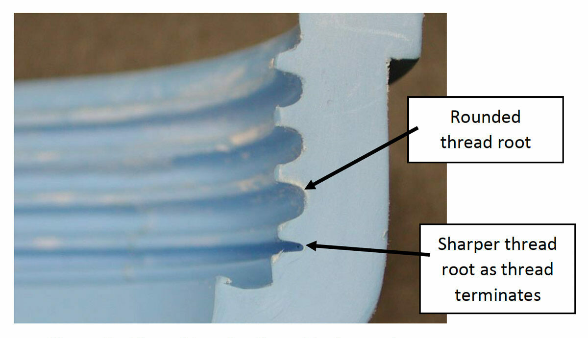
Figure 2. Thread termination with sharp edge.
A final consideration is when a thread is designed to terminate near a load bearing flange (Figure 3). In this case, the male thread is designed to bottom out against a rubber washer on the flange, which then exerts an additional longitudinal load along the threads. This additional loading subjects the bottom-most thread and the thread-flange transition to higher stress, which is then incremented by the sharp nature of the geometrical transitions. Therefore, in these design situations, it is recommended to include a smooth transition with a large radius between the thread and flange (Figure 3 – Right) instead of terminating the thread directly into the flange (Figure 3 – Left).
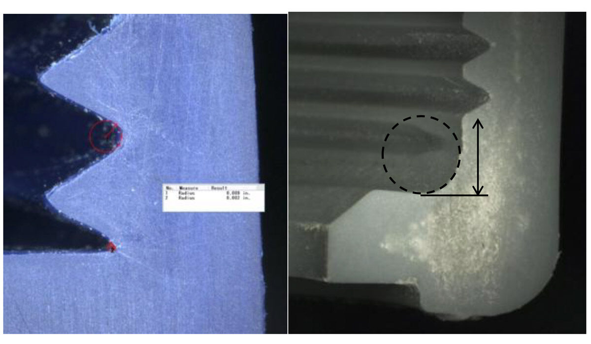
Figure 3. Example of threads terminating at flange (left: termination directly into flange; right: termination away from flange and large radius)
The design of threads in plastic components must go beyond basic engineering standards and beyond replication of metal threads. The geometry of the thread is an important consideration, but the design process should not stop there. The combination of wall thickness, material properties, thread geometry and thread termination should be considered concurrently. It is not only important to study the distribution of stresses along the threads, but also to consider the long-term creep effects of the plastic and the residual stresses from manufacturing.