In this installment of the Hunting for Insight series, the focus is on the Air Traps result, an output that guides critical design decisions around cosmetic quality, gate placement, and tooling such as parting line splits, venting, ejector design, as well as the use of mold inserts. This article will explore how air trap simulation contributes to these important areas.
What is an Air Trap, and Why Should Designers Care?
An air trap is a location where air becomes trapped ahead of the advancing flow front or behind converging flow fronts because there is no path for the displaced air to escape. Depending on the flow conditions, air can either be trapped between plastic and the mold steel, such as at the end-of-fill location(s), or it can be fully encapsulated in plastic. Air traps can cause structural or aesthetic defects on a part that are not usually able to be processed out. Typically, trapped air results in a small hole or a blemish on the surface of the part. In some cases, compressing the air increases the temperature to the point where plastic burns or degrades, which is also called dieseling. Not only can burning cause black specs or streaks on the part surface, but it can also damage the tool, see Figure 1.
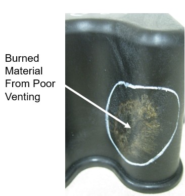
Figure 1 shows an example of a burn mark near and end-of-fill region on a part due to dieseling.
Venting: Creating a Path for Air to Escape the Mold
When the mold closes at the beginning of the cycle, air is present in the empty cavity. As the molten plastic advances through the mold, it pushes the air into the ends of auxiliary features and towards the last places to fill. Since the majority of the air is pushed to the end-of-fill locations, molds will commonly have parting line vents around the perimeter of the part. However, if venting is not placed in these areas, the air will have no means to escape the mold cavity.
Vents are design features of the mold that integrate shallow openings that allow air, gases, and volatile byproducts to escape the cavity, as the molten plastic is injected into the mold. Proper venting allows air to escape out of the mold cavity ahead of the melt front, which helps minimize the potential for short shots (incomplete fill), weld line formation, and poor part aesthetics.
In practice, vents are typically placed along the parting line, at the last places to fill, or at the tops of ribs, bosses, and other auxiliary features. Vents are sized to be deep enough to displace air but shallow enough to prevent molten plastic from flashing out of the cavity. Typical vent depths are about 0.0010” but can vary from 0.0005” – 0.0025” depending on the resin. Common practice is to vent as much of the perimeter as possible, so if vents at the end-of-fill locations become clogged, air can still escape along other vented areas.
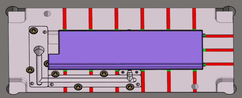
Figure 2 highlights perimeter parting line vents in a tool (green), as well as the vent reliefs (red).
Where Air Traps Commonly Occur
Some air traps are more easily addressed than others. When trying to identify areas that might need special attention to venting, the part and mold designer should understand where on the part is the last place to fill. If these locations occur along the parting plane, venting can typically be integrated without much effort. However, air traps can also occur in auxiliary features such as snap fits, ribs, bosses or other complex geometry often associated with slides or side actions. These features are not formed at the parting line of the mold, and will require utilization of mold design features such as ejector pins, ejector blades or sleeves. Strategically placing ejector features in the location of trapped air can allow air to escape, although these areas may require more frequent maintenance to prevent burning and short shots.
Alternatively, the mold designer can integrate stepped parting lines, or mold insert split lines to allow the air to escape. Slides or side actions can break up the continuity of perimeter venting, making air escape more challenging. Identifying these situations early in the design stream allows designers to explore methods such as gate positioning, flow leaders, lifters, or stepping the parting line to mitigate air traps. The integration of these features can affect the initial investment of the mold, but are critical for processing and mold durability.
Air traps can also form, as a result of varying wall thicknesses within the part design. If the wall thickness variation is large enough, or if there is not enough of a transition from thin to thick areas of the molded part the molten plastic will preferentially flow through the thick areas, and hesitate in the thin areas. This preferential flow phenomenon is often referred to as race-tracking, and can create large air traps that are difficult to vent. If the race-tracking is severe enough, the molten plastic can create an air trap in the thinner areas of the mold. This can further weaken the part by creating a weak weld line, or a short shot in the part. Depending on the size and location of the air traps formed as a result of race-tracking, they could be vented using ejector pins, or mold inserts. See Figure 3.
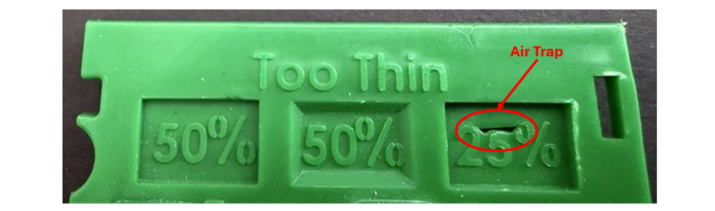
Figure 3 shows an example of recessed pockets on a part. When the pocket is only 25% of the nominal wall, an air trap forms in the center of the pocket.
However, if the air trapping is severe enough, it may require integration of porous steels, such as Porcerax, or 3D printed inserts. Both options are non-ideal as they will influence the cost of the initial investment on the mold, and will increase the cost for mold maintenance as well.
The position of air traps will change depending on how the molten plastic fills the cavity. Therefore, designers can use the Air Traps result to help finalize gate location decisions. Changing the gate location may be the easiest way to reposition air traps in the cavity to ventable regions of the tool without making big changes to the part and mold design. Therefore, gate location selection is often the first step to ensure that the last-to-fill regions align with ventable areas of the tool.
Although air traps are difficult to process out, processing conditions can influence their formation. In cases where hesitation contributes to a wrapping flow front, increasing the injection velocity can sometimes reduce hesitation enough to mitigate the air trap. However, this should not be a primary solution, as most air traps are driven by geometry and flow paths rather than process settings alone. Filling faster may also increase the pressure the air exerts on the melt front and make it more difficult to fill the area and increases the risk for burning or short shots.
As the previous sections have highlighted, managing the air flow and air traps is an important variable that will influence the mold cost and overall process window. Therefore, it becomes very important for a designer to understand where air might be trapped in the mold to help them drive decisions on gate location, and final part design. Understanding where air traps are predicted to occur can also facilitate their conversation with their tooling or molding partner when evaluating different strategies on parting line placement, or ejector pin placement
The Air Trap Result: What You’re Looking At
A good way to identify potential areas that will need to address air traps in a part is by looking at the Air Traps result within an injection molding simulation. The Air Traps result visually maps where converging flow fronts are predicted to trap air during the filling process. This result is generated during any Fill or Fill+Pack analysis and is available across all mesh types—midplane, dual domain, and 3D. Midplane and dual domain results only display air traps as surface-level circles (displayed on the shell of the part). Whereas 3D meshes also offer a through-thickness view, which is vital for thicker parts or structural features [Figure 4].
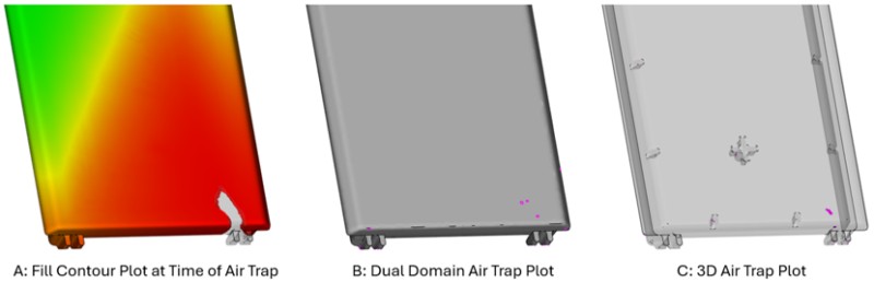
Figure 4 shows the location of an air trap on the show surface of a cover housing (A) with both display types: Dual Domain surface plot (B) and the through-thickness 3D plot (C).
The default plot uses a colored scale bar, intended to represent the probability for an air trap to occur in that particular location. However, this plot is best used as a general map of the possible locations of air traps. Changing the color map in the plot properties from rainbow to a brighter single color will make it easier to see these locations. As seen in Figure 5.
Once an air trap is identified using the Air Traps plot, its presence should also be confirmed by reviewing the flow front progression in the Fill Time plot. The Air Traps result alone indicates where air may be trapped, but the Fill Time plot will help explain why it happens by showing how the melt advances, hesitates, or wraps around features. By reviewing the filling contour spacing leading up to an air trap, designers can determine whether flow direction, hesitation, race-tracking, or abrupt changes in wall thickness are contributing factors. (Click here to read more about the Fill Time Plot)
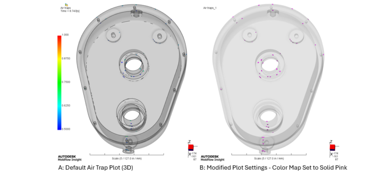
Figure 5 shows a map of all the predicted locations of air traps. Figure 5A highlights the default settings and Figure 5B shows the air traps set to pink, making them easier for the designer to see.
A tool designer can use an image like Figure 5B to highlight all areas of the tool that need venting. The Air Traps result is a great tool for creating a map of potential locations of air traps, but is up to engineering judgement to dig deeper and determine the potential severity of the air trap and how it should be addressed.
Summary
Air traps are fundamentally design-driven issues that can be identified early in the development process using the Moldflow Air Traps result. Waiting until tooling is underway or complete to evaluate these conditions often limits the available solutions, as air traps are rarely something that can be corrected through processing alone. When the Air Trap result is evaluated alongside the Fill Time and Weld Line plots, designers gain a much clearer picture of filling behavior, venting feasibility, and the true risk of cosmetic or structural defects. By hunting for insight early, designers can drive informed part, assembly, and tooling decisions and design out the problems that would otherwise “burn” them later.