Many elements must be considered when designing an injection mold for a new molded plastic product. One of the first decisions that can have a radical effect on the molding process, and the quality of the finished molded part, is gate location selection. Selecting an appropriate gate location determines the pattern in which the part fills, the pressure required to fill the part and potential for air traps and other defects. This article will look at the geometries, filling patterns, effects on processing, and potential defects to take into consideration when deciding on a gate location.
Thick to Thin
One of the more basic guidelines for selecting the gate location is to place the gate in the thickest region of the part. The reason for this is that as the part cools, the material freezes off in the thinner areas first. Gating into a thinner cross-section would result in the thicker regions of the part remaining molten after the thin geometries are frozen. Conversely, gating into the thickest cross-section of a part would allow for packing pressure to be applied to those areas after the thinner geometries have frozen. Applying packing pressure longer to the thicker geometries of the part, will help to reduce the experienced volumetric shrinkage and potential for voids and sink marks in those areas. As a rule of thumb, it is not suitable for the gate thickness to exceed 80% of the immediate wall thickness. Locating a gate on thicker geometries allows for greater flexibility in appropriately sizing the gate and avoiding undesirable conditions such as excessive shear rates and shear stresses.
Unidirectional Flow
Another issue to keep in mind with gate location selection is the resulting flow pattern during fill. Unidirectional flow is where the flow of material travels in a single direction, rather than changing directions and converging. Ideally, the fill pattern would flow through the gate and minimize any changes in flow direction. Although, complex part geometries can sometimes make this unrealistic. A unidirectional filling pattern is beneficial as it can improve the mechanical properties as the polymer molecules orient in the direction of flow.
Figure 1 illustrates a unidirectional and balanced fill pattern in example A, and an unbalanced filling pattern that changes directions in example B. The part geometries are the same for both examples. However, the gate is in the top center of the part in example A, whereas, the gate is located on the bottom edge of the part in example B. The filling pattern in example A is more desirable as the flow front fills across the part geometry uniformly, and is balanced in reaching the ends-of-fill.
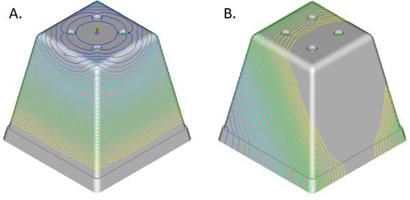
Figure 1: Unidirectional vs Non-Directional Flow
Air Trapping
Along with achieving unidirectional flow, it is important to select a gate location that results in a fill pattern with an end-of-fill condition at the parting line. By doing so, allows for trapped air to escape through venting at the parting line and prevents problems such as air trapping in the injection molding process. Air trapping can result in visual defects in the finished part such as surface blemishes and burn marks, bubbles, and short shots. An example of burn mark defects in a molded part can be seen in Figure 2. Looking again at Figure 1, it can be seen how the uniform flow front in example A would push any air in the cavity towards the parting line, while the wrapping flow fronts in example B have a higher probability of trapping air in the mold cavity.
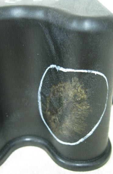
Figure 2: Example of a burn mark defect in a molded part.
Pressure to Fill
The greatest contributor to the required pressure to fill a part is the length of flow. Choosing a gate location that minimizes the flow length to fill the part, will in turn, minimize the pressure to fill the part. Maintaining a low injection pressure ensures the process will not be pressure-limited, and instead result in a wide processing window. Figure 3 illustrates how much the injection pressure needed to fill the part can change, just by altering gate location selection. The gate location in example A represents the shortest flow length to fill the part, whereas, the location in example B has a much longer flow length. The longer flow length results in a significant increase in pressure to fill the part.
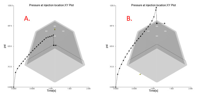
Figure 3: Difference in Injection Pressure due to Gate Location.
Gate location selection has a direct impact on the process parameters required to fill and pack a plastic part. Fill pattern, injection pressure, potential for air trapping and other defects need to be considered when selecting a gate location. Injection molding simulation software like Autodesk Moldflow can help to vet out the options for potential gate locations before building a mold. Stay tuned for a follow-up article on how injection molding simulation software can be used to select the optimal location for gating plastic parts.