In this installment of the Hunting for Insight series, the focus is on the Weld Line result, an output that guides critical design decisions around gate placement, feature layout, part strength, and cosmetic quality. Understanding the significance of Weld Lines in Moldflow is crucial for making these informed decisions.
What is a Weld Line, and Why Should Designers Care?
Weld lines, also called knit lines or meld lines, form when two or more flow fronts meet during the filling phase of the injection molding process. They commonly appear around design features like through-holes, bosses, and ribs. They also can form between gates, or anywhere the molten plastic flow path splits and rejoins.
To a designer, weld lines aren’t just computer-generated lines on a Moldflow plot that may have a skewed appearance on the molded parts, they represent inherently weaker areas that could increase the potential for failure. Weld lines are locations where the polymer chains may not fuse adequately, resulting in reduced mechanical strength due to poor molecular entanglement. In fiber-reinforced materials, the problem is compounded by disrupted fiber orientation, where fibers that would normally align with the flow become misaligned or cross-oriented at the weld, weakening the interface further.
Cosmetically, weld lines can appear as visible seams, streaks, or gloss variation, which are especially problematic on cosmetic parts and highly visible surfaces. Functionally, weld lines often lead to unreliable performance in load-bearing features like snap-fits, clips, through-holes, screw bosses, and other mounting features. Understanding where they form, why they form there, and how strong they are is key to delivering a part that performs consistently, molds efficiently, and avoids costly rework after tool steel is cut.
The Weld Line Result: What You’re Looking At
The Weld Line result visually maps where flow fronts are predicted to converge during the filling process. It is generated during any Fill or Fill+Pack analysis and is available across all mesh types—midplane, dual domain, and 3D. Midplane and dual domain results only display weld lines as surface-level curves (displayed on the shell of the part). Whereas 3D meshes also offer a through-thickness view, which is vital for thicker parts or structural features, Figure 1-C. The solid line plots shown below are good tool to map out the locations that weld lines form in the part.
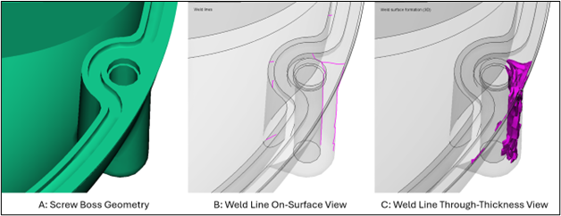
Figure 1: The location of a weld line on a screw boss feature with both display types: Weld lines plot (B) and the Weld Surface Formation (3D) plot (C). This shows the difference between displaying the weld line on the parts surface (B) and the weld line formation through the thickness in 3D (C).
What Information Can the Weld Line Plot Provide?
While the location of the weld line is important information to have as a designer, the conditions under which the weld line formed can be just as important. The weld line result can provide data on the angle of formation, the melt temperature during formation, and the pressure applied to the weld line during both filling and packing. These factors have all been shown to be critical process parameters that influence the integrity of the weld line, both from a cosmetic and structural perspective.
While Moldflow uses a single term “Weld line” plot, there are several names under which the industry uses for these molding artifacts. Weld Lines, flow line, knit lines, or meld lines are all used to refer to the same molding defect. To some, a differentiator is the angle the flow fronts rejoin at the interface, Figure 2. A weld line forms at a narrow angle, where the flow fronts meet in a more head-on orientation. This abrupt rejoining tends to produce a weaker interface, where there is little ability for the molecules or fibers to bridge the interface. A meld line is still a weld line, but the angle of formation is less abrupt and promotes greater molecular entanglement, which can lead to higher strength and toughness. The weld line plot can provide an indication of the angle of formation, and how quickly the flow fronts change direction to increase that angle of formation. The plot will generate weld lines that form with normal angles between 0° and 135°. The weld line location result will not display a weld line that is greater than 135°. Therefore, it is always important to review the mold filling result, and not rely on this plot alone when assessing potentially weakened areas.
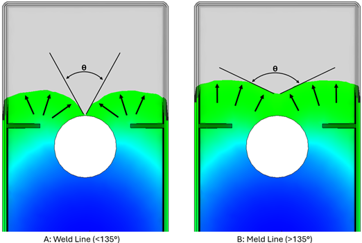
Figure 2: The weld line formation angle is an important parameter to understand the integrity of the weld line. This angle is also often used to differentiate between a weld line and a meld line. Figure 2 shows the angle at which a weld line forms around a through-hole. When the weld line first forms, close to the hole feature, the angle is a very narrow angle (A). As the flow fronts progress, the angle gets wider, and the strength of the weld line increases (B).
A flow analysis can produce an angle of formation plot that highlights what angle the converging flow fronts are at when the weld line forms. However, the angle at which weld lines form can also be evaluated visually when overlayed with a fill time plot.
Overlaying the fill time plot with weld lines can also help you evaluate if the weld line prediction is actually occurring in that location. It can also help you understand if there is potential for air trapping at that location that would inhibit the fusion of the weld. Looking at the weld lines with the fill pattern overlayed can also help determine what is causing the weld line and answer questions like; is it from a design feature like a through hole, close rib spacing, or from hesitation due to poorly placed thin sections in the part?
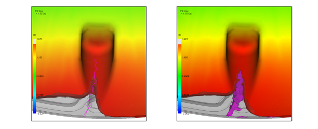
Figure 3: The solid weld line location plots overlaid with the fill time plot. These display styles can help confirm what geometry is causing the weld line, in this case a screw boss. They can also help visualize the angle that weld lines form, rather than evaluating the angle based off of a colored scale bar.
Two other important datapoints that can influence the integrity of the weld line, are the temperature of the molten plastic when the weld line forms and the pressure that reaches the plastic at the end of fill and during packing. Generally speaking, if there is no air trapping at the interface, and venting in the tool is sufficient, a higher molten plastic temperature and higher pressures at the weld line help promote molecular entanglement that can lead to a more robust performing weld line. Both of these parameters can be quantified using the weld line result, and allow an analyst to provide an initial assessment of the risk of a poor weld line forming.
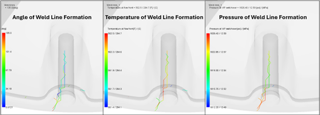
Figure 4: From left to right, the weld line angle of formation, temperature and pressure overlay plots. These plots allow the designer to evaluate the relative strength of the weld line based off of the conditions it was formed at.
Together, these additional metrics turn the Weld Line result from a static defect map into a design tool—helping you understand not just where something is happening, but why, how, and what you can do about it.
Why Designers Should Use the Weld Line Result and Not Rely on Process Optimization
While designers and molders generally understand that weld lines are inherently weakened areas, the reduction in expected mechanical properties can vary based on materials. Unfilled materials like ABS, PP, or PC can actually have very good retention in yield strength and modulus at a weld line, if process and tooling are optimized. However, they will often experience a reduction in the elongation at break, Figure 5. For fiber-filled materials there is generally both a reduction in strength and elongation at the weld line. This reduction can be as large as 50-60% from areas remote from weld lines, Table 1. This variability in the behavior of the weld line highlights one of the reasons that proper material selection is critical for every application.
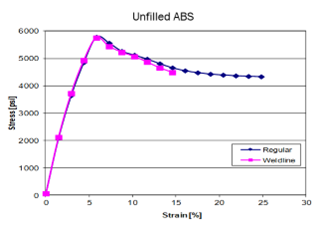
Figure 5: The stress versus strain curve of an unfilled ABS resin with a single gate and no weld line vs dual gates that created a weld line in the middle of the tensile bar. There was a significant reduction in elongation, and a loss in overall toughness and impact strength with the weld line bar.
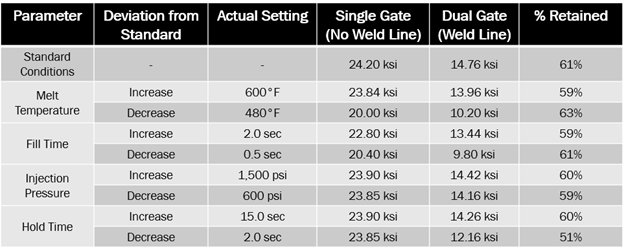
Table 1: Tensile bar data published by LNP where they molded 30% glass fiber filled PA66 with a single gate and with opposing dual gates that created a weld line in the middle of the tensile bar at various process settings. During testing it was discovered that not only was the overall yield strength significantly reduced with the weld line, but the process settings had little effect on the tensile strength at the weld line.
Based on the previous section, a designer may assume that the integrity of the weld line can be optimized through processing. However, that assumption is often challenged during mold qualification and can often lead to aggressive processing conditions that lead to other issues. Therefore, it is important to understand that you can’t really process out a weld line and its strength. This is especially true for fiber-filled materials, as is shown in Table 1. Therefore, the design of the part and tool becomes the best avenue to move the needle on designing for weld lines.
Diagnose Critical Weak Points Early
A key question during early design reviews is whether weld lines are forming in locations that are highly cosmetic or will see structural loading. For structural integrity, areas such as bosses, ribs, snap fits, and latches, must be examined closely, since weld lines here can directly impact performance and reliability. In cosmetic regions, weld lines may appear as seams or streaks that reduce visual quality, while in shutoffs or sealing features they can compromise proper fit and function. The Weld Line result enables designers to spot these risks while changes are still feasible, allowing for corrective action before tool steel is cut.
Feature Sensitivity: What Tends to Cause Weld Lines?
Certain part features are especially prone to generating weld lines, and recognizing them early can save considerable rework later. Bosses and holes are classic weld line generators and often end up in structurally demanding locations. Multiple ribs, particularly when tightly spaced or positioned in-line with the flow path, can also create convergence zones for the flow fronts. Thin-to-thick transitions can cause disruptions to the flow such as hesitation and racetracking that cause a weld line. Geometry changes may be needed to mitigate weld lines from forming due to these features, but are often very expensive to re-tool if the weld lines are found at the start of production rather than the DFM phase. The weld line plot in Moldflow can help flag these risks before the design is finalized.
Drive Gate Location Decisions with Intent
Another benefit of looking at the Weld Line results is because gate placement directly influences where the weld lines form. Therefore, the Weld Line result helps drive the gating strategy, and can help the molder and designer find a reasonable tooling solution that will produce a robust part. In addition to defining all the functional part and assembly features, designers should drive decisions regarding the gate location(s). Additionally, the designer is in the best position to understand how the part design could be modified to function, if a weld line needs to be moved and moving the gate is not an option. By driving the simulation earlier into the design process, the robustness of the change can be improved while minimize the cost of making the change.
Summary
Weld lines are an unavoidable reality of injection molding, but with the right tools and insight they don’t have to become a failure point. Moldflow’s Weld Line result gives designers the ability to predict where welds will form, evaluate their severity, and understand the conditions that drive their formation. This knowledge empowers better gate placement, smarter feature design, and proactive planning for materials and applications where weld lines pose the greatest risk. Ultimately, integrating Moldflow and weld line analysis into the design phase ensures more reliable, and more cosmetically acceptable parts, before tool steel is ever cut.
Hunting for Insight? A Practical Guide to Understanding Moldflow Results: Weld Lines
Hunting for Insight is a series where we look at common results from Moldflow simulations. Whether you are a full time Moldflow analyst, occasional user, or are a program manager that reviews a handful of reports a year, the goal of this series is to provide valuable context for the different results, and explain how they can be used to provide actionable insight when you are designing your plastic part, or injection mold.
Check out a previous installment on Fill Time here: Hunting For Insight – A Practical Guide to Understanding Moldflow Results: Fill Time