Injection molding has been the dominant process for producing complex, tight tolerance plastic parts. The plastic resin experiences aggressive conditions during the process, which is driven by the need to economically manufacture these components while maintaining the desired tolerances and surface aesthetics. From the shear deformation the polymer molecules experience as they are being melted and injected into the mold, to the rapid cooling of the resin as it comes into contact with the cold mold wall, the orientation and extension of the polymer chains change significantly from its original, relaxed state. Additionally, the polymer chains cannot always get back into the state they want to be in, which leaves those areas of the part in a non-ideal condition that develops stress from molding. This stress is often referred to as residual stress or molded-in stress. The presence of these stresses is not always obvious, and has been largely ignored in the past due to the difficulty in quantifying them. However, these residual stresses can be significant and can lead to performance issues for molded parts such as dimensional stability, optical distortion, cracking, and part brittleness. This article will discuss how residual stresses develop and how they can be quantified.
How Does Residual Stress Develop?
During the injection molding process, the molten resin is injected into a mold to form the part. Prior to injection, the long polymer chains are entangled and in a relatively random orientation. However, during injection these same chains are subjected to shear forces that cause them to align and stretch in the direction of flow. While this alignment and elongation have some benefits, such as reducing the viscosity of the polymer melt, it also places the polymer chains in a stressed state. Once the polymer melt touches the cold mold wall, the polymer chains are frozen in this elongated state and a residual, tensile stress is developed in the part, Figure 1.
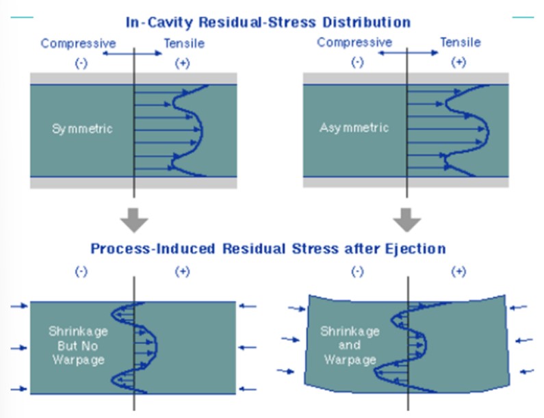
Figure 1: Schematic of Residual Stress Development in Injection Molded Part. Source: Autodesk Moldflow Design Guide.
Additionally, the molten plastic continues to flow inside this frozen material, and the polymer chains immediately adjacent to this layer are also placed in a state of tension. The thickness and magnitude of this tensile stress zone are often driven by how fast the mold is filled and the mold surface temperature. These residual stresses can be further magnified at sharp corners in the part or at core pins, where the polymer chain initially freezes upon initial contact, but then is further stretched as the material continues to flow around the feature.
Stresses continue to develop in the molten resin during the packing stage. The pressure that is applied during this stage, to compensate for the volumetric shrinkage of the polymer melt as it solidified, restricts the polymers ability to get the chains in their preferred orientation and impart stress. This is a particular problem near the gate, where hot material is continually being introduced into the mold and the injection pressure is highest. These conditions create the most restriction to the polymer mobility, and do not allow the polymer chains to relax into their desired state.
Residual stress can also be developed in areas remote from the gate, if they cannot be adequately packed out. If pressure cannot be maintained on the polymer melt until it has cooled sufficiently, the polymer will exhibit a greater amount of shrinkage than the surrounding area. This shrinkage gradient will cause stress to develop as the polymer chains are stretched to occupy this volume. Sometimes, there are visible cues such as warpage, sink mark formation or voids. However, other times there is no visual sign that the plastic part is under stress. Regardless of the reason for stress, if the polymer molecules cannot get into their preferred orientation during the molding cycle, they will try to relieve this stress and move into their preferred state after being ejected. If enough movement of the chains occur, cracking and crazing can occur, which can weaken the part. Additionally, these stresses take time to dissipate, and will superimpose on any operational stresses the part experiences while in service. Therefore, the impact and long-term creep performance, as well as the chemical resistance of the product can be adversely affected.
How to Quantify the Residual Stress?
The combination of more demanding performance criteria, longer service life, and increasing part complexity have forced part designers to better understand the magnitude and distribution of residual stress in their molded parts. Therefore, they must have a method to quantify these stresses. With the ability to quantify the residual stresses, the designer or manufacturer can optimize the part or mold design, and process to yield a better product. There are numerous methods that can be used to help provide an estimate of how much stress exists in the part. A few of these methods are presented below. While the list is not exhaustive, it provides an initial basis for the reader to understand how they might quantify the residual stress in their part.
Photoelastic Stress Analysis (PSA)
If the component is a relatively simple geometry, and is manufactured from an amorphous resin, photoelastic stress analysis could help provide a measure of the residual stress present in your molded part. This method relies on measuring the birefringence of polarized light or how the velocity (speed and direction) of the light changes as it passes through the plastic specimen. This birefringence generates a color contour pattern on the part that relates to the amount of stress that exists through the cross-section of the part, Figure 2.
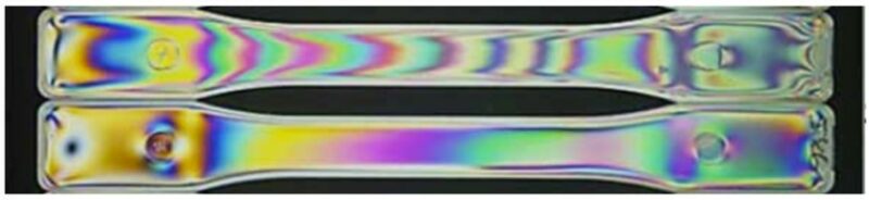
Figure 2 Image Highlighting the Birefringence Pattern in Polycarbonate Tensile Specimens using Photoelastic Stress Analysis.
Often times, this method is used to qualitatively evaluate the stress state in the molded part. The color generated and the spacing of the different color contours can help identify areas of high stress. While this method can provide directional input on how the residual stress changes for the part, it cannot easily be used to quantify the stress in the part. Additionally, the color contour provides a composite stress state through the cross-section of the part and does not distinguish between compressive or tensile stresses. This method can be used to provide more quantitative results. However, a sophisticated piece of equipment called a polarimeter is required, and material characterization is required to identify a material constant. This material constant is unique to each material and requires a non-trivial characterization procedure.
While this method can be attractive as a low cost option to qualitatively evaluate the stress state of a physical molded product, there are some limitations. As stated previously, the part geometry has to be a relatively simple, generally plate-like structure, to best use this method. While cylindrical specimens can be accommodated and analyzed, the variable entrant angle of the polarized light and the viewing angle of the specimen reduce this method to a more qualitative evaluation. The specimen must also be manufactured from a transparent material that allows light to pass through it. Therefore, this is not an effective method for filled or semi-crystalline methods. However, this method even has limitations for some amorphous resins, such as acrylic that does not exhibit this birefringence pattern even when stress is present. This can limit the usefulness of this technique to only certain resins.
Solvent Stress Test
If the designer is more interested in the stress developed at the surface of the part, and the implications it may have on the chemical resistance of the part, an alternative may be to perform a solvent stress test. This test takes the molded specimens and submerges them into different concentrations of solvent mixtures that are known to cause surface cracking at different stress levels, Figure 3.
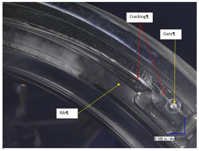
Figure 3: Micrograph Showing Cracking at the Gate and Base of Rib after Exposure to Solvent Stress Test.
The exact solvent and concentrations levels are specific to each resin. However, this test allows for more complex shapes to be tested and can help provide an indication of stresses developed at thickness transitions, ribs and bosses. It can also be an effective method at quantifying stresses near the gate of the part, and how processing may influence the localized stress in these areas.
The ability to quantify the stress state in these more complex parts, make this a nice economical method as compared to the PSA test. The limitations of this method include the fact that such a test has not been developed for every resin or polymer family, and most of the tests used are only for amorphous resins. The reason for this is that the amorphous resins are more likely to exhibit sensitivity to solvents, as compared to semi-crystalline resin. Additionally, from a practical stand point, it is easier to notice the crazing on transparent resins. Therefore, the ability to distinguish crazing at the different solvent concentrations is enhanced. Another limitation is that this method can only provide indications of the stress state at the surface of the part. It cannot directly measure the stress in the core of thick areas that may not be adequately packed out, and may be subjected to high tensile stresses.
The test can be extended to polymer blends and other amorphous resins that have not been characterized. However, development of these tests require extensive knowledge of the material and specimens at known stress states. The Madison Group’s knowledge and experience with this test method allows us to assist in evaluating and developing such test methods.
Injection Molding Simulation
The previous two methods presented focused on measuring the residual stress on physically molded specimens. Additionally, the test methods have been restricted to unfilled, amorphous resins. The last method uses a proactive approach to mitigating potential areas of high residual stress by using simulation. By using injection molding simulation, the part design and injection molding process can be analyzed and optimized prior to manufacturing any mold or parts. This proactive approach can allow the designer much more freedom or to account for the high-stress state when optimizing the design. Using simulation also allows the stress at both the surface and core of the part to be analyzed, Figure 4.
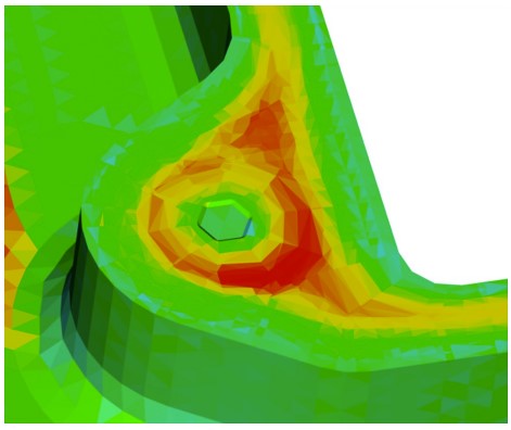
Figure 4: Predicted Residual Stress Distribution Through the Thickness of an Injection Molded Boss Using Simulation.
Additionally, the stress gradient through the thickness of the part can be examined. This method allows for the high-stress regions in the core of the part to be better identified and quantified. Finally, this method allows any resin part combination to be analyzed. It does not matter if the resin is transparent, semi-crystalline, filled or unfilled. As long as the material characterization properly represents the material behavior, any material can be analyzed.
The major limitation of this method is that the stresses predicted are just that, predictions. Depending on the material characterization or the level of detail included in the simulation, the actual stress values and distribution could be different than those simulated. Additionally, the predicted stresses in thick regions that are not adequately packed out will likely overestimate the stress. This overestimation is a result of the solver’s inability to create breaks in the mesh where voids may actually form in the part. Even with these limitations, the use of simulation to provide an approximation of the residual stress state in the part allows engineers and designers to make better decisions regarding material selection, part design and processing.
As higher performance demands are being placed on plastic components, designers are forced to push the envelope of best part design and need to account for all potential sources of stress. Finding efficient and effective methods at characterizing the stress created during manufacturing can lead to better material selection, more robust part performance, and lower overall cost due to fewer part failures. While the lists provided here are not exhaustive, it can at least start the discussion on the need for such testing in the future during product validation.