Abstract
This paper focuses on how computer aided engineering (CAE) tools allow engineers at early stages of product design to predict and optimize mold filling, residual stress, structural response and post-processing shrinkage and warpage of the final part. The material properties and characteristics of the final part are highly influenced by the flow pattern, temperature and curing of the material inside the mold. The use of these tools has been used to solve design problems at early stages and avoid expensive and time consuming trial-and-error procedures and mold modifications resulting after the mold is manufactured.
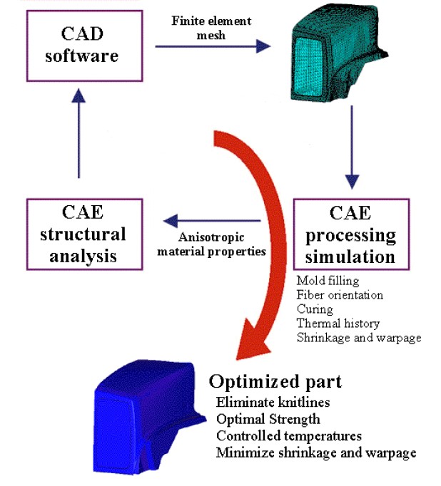
Figure 1. The CAE analysis of compression molded parts.
Introduction
CAE analysis tools offer the tremendous advantage of enabling design teams to consider virtually any molding option without incurring the expense associated with manufacturing and machine time. The ability to try new designs or concepts on the computer gives the opportunity to eliminate problems before beginning production. Additionally, designers can quickly and easily determine the sensitivity of specific molding parameters on the quality and production of the final part.
This CAE virtual design offers tremendous flexibility to determine the effects of different initial charge locations, gating scenarios, geometric features, and different molding and processing conditions on the moldability and quality of the final part. Furthermore, CAE tools allow these virtual designs to be completed in a matter of days or even hours rather than the weeks associated with experimental trial and error. When CAE is used early in the design stage the cost savings are substantial not only because of time savings, but also the avoidance of expensive and common last minute mold modifications and tweaks.
The CAE analysis cycle of compression molded parts is shown in Fig. 1. An analysis starts with the creation of a computer solid model and a finite element mesh of the mold cavity. After the processing conditions are specified, mold filling, fiber orientation, curing and thermal history, and shrinkage and warpage can be simulated. The anisotropic material properties calculated by the simulation can be used to model the structural behavior of the part. If required, part design, gate or initial charge location and processing conditions can be modified in the computer until an acceptable part is obtained. After the analysis is finished an optimized part can be produced with reduced knitlines, optimized strength, controlled temperatures and curing, and minimized shrinkage and warpage.
Background
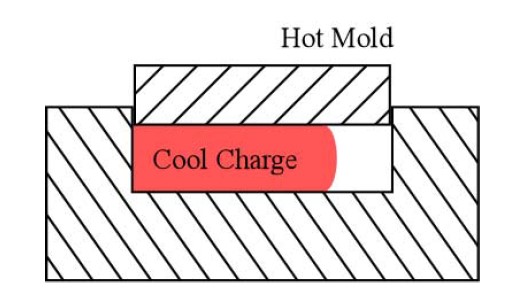
Figure 2. Compression molding process.
Process Overview
The compression molding process is widely used in the automotive, aerospace, sporting goods, and electronics industries to produce parts that are large, thin, lightweight, strong and stiff. Compression molded parts as shown in Fig. 2 are formed by squeezing a cold glass fiber reinforced polyester charge, known as sheet molding compound (SMC), between two heated cavity surfaces. The usually 25 mm long reinforcing fibers are randomly oriented in the plane of the sheet and make up for approximately 25% of the molding compound’s volume fraction. Generally, the mold is charged with 1 to 4 layers of SMC, each layer about 3 mm thick.
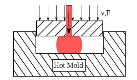
Figure 3. Injection-compression molding process.
An alternate process is injection-compression molding. As shown in Fig. 3, injection-compression is a hybrid molding process that incorporates both the features of injection and compression molding. In this case a bulk molding compound (BMC) is injected into the mold and then compressed. BMC materials typically have shorter glass fibers than SMC and accordingly exhibit lower structural properties. The main benefits of injection-compression molding are automation and shorter cycle times.
Mold Filling
Mold filling is used to study the advancement of material inside the mold cavity starting with the initial charge shape or injection point and finishing with the full mold. This information is used to predict cycle times, compute pressure balance, ensure complete filling of the mold, predict knitlines and detect air entrapment. Before the mold design is finalized the engineer can avoid future operating problems by simulating mold filling for varying molding conditions, mold thickness and for a series of charge configurations or injection gates.
Knitlines and trapped air are important in predicting the structural integrity of the final part. These anomalies can cause weak points and surface finish problems that can lead to cracks and failure of the final part. A knitline occurs when distinct flow fronts meet each other not allowing fibers to bridge between the two fronts. Air entrapment occurs when two flow fronts meet around an unfilled area leaving a void on the final part.
To model the mold filling of compression molding of thermoset materials the Barone & Caulk flow model is used [1]. This model assumes that the material deforms uniformly through the thickness with slip occurring at the mold surface. The flow phenomenon of thermoset materials has been well documented by Osswald [2]. The main assumptions of the model are as follows:
- The mold is thin with respect to the surface dimension
- The closing speed for the compression phase is known
- The molding compound is treated as an incompressible isotropic viscous fluid
- The non-isothermal conditions in the mold form a lubricating layer at the mold surfaces and the material is dominated by plug flow. This plug flow can be described by a lubrication analogy with kinematic friction
- There is no leakage at the edges of the mold
The resulting Barone & Caulk’s based mold filling algorithm has been extensively tested with a host of experimental studies and practical applications [2-5]. Osswald, et al [3], compared a mold filling simulation based on this algorithm with a short-shot experiment for the hood of a Corvette. To compression mold this hood three SMC charges were used. One placed on the middle of the hood and two placed on the headlamps. Fig. 4 shows the comparison between the mold filling simulation and the experiments.
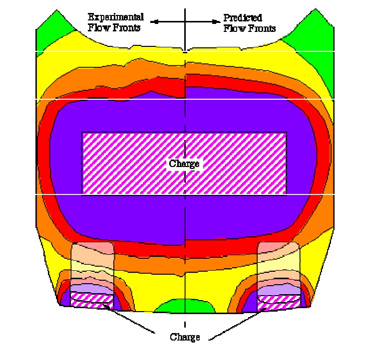
Figure 4. Simulation (right-hand side) and experimental (left-hand side) results for mold filling of the hood of a Corvette.
Fiber Orientation
As depicted in Fig. 5, material flow and deformation in the mold causes the reinforcing fibers to rotate and orient to create a part with anisotropic properties. This fiber orientation greatly affects stiffness and strength of the final part, and is the major cause for warpage after the part is cooled and removed from the mold. High degrees of fiber orientation become a problem in places where peak stresses are encountered such as around hinge or fastener attachments.
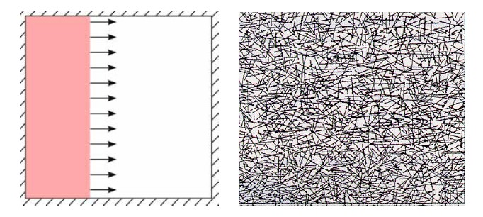
Figure 5. Fiber orientation induced by the material flow in the mold.
In CAE analysis of compression molded parts predicting orientation is important to understanding and computing mechanical properties of a part. The most widely used model for fiber orientation in compression molding is the Folgar-Tucker model [6]. This model considers the material’s velocity gradients, strain rates, and fiber-fiber interaction. Using a fiber orientation algorithm based on the Folgar-Tucker model, Osswald, et. al., [7] were able to successfully describe the anisotropic mechanical properties of an oriented composite.
Shrinkage and Warpage
Shrinkage and warpage of a compression molded part is a consequence of fiber orientation and residual stresses developed during processing. The formation of residual stress is attributed to two major coupled factors: curing and thermal history. Therefore, cure and temperature history along with fiber orientation are essential to understand and control the final shrinkage and warpage of the part.
The autocatalytic curing reaction undergone by unsaturated polyester and vinyl-ester materials used in SMC and BMC can be represented with an empirical model such as the one developed by Kamal and Sourour [8]. Using the Kamal-Sourour model for curing and the Folgar-Tucker model for fiber orientation Osswald, et. al. [5], successfully predicted the final shape of a SMC compression molded hood scoop and pick-up truck rear fender. The deformation of the fender with respect to the mold was measured at two points after cooling and de-molding. These results are shown in Fig. 6 where the final shape predicted by the simulation is in red and the mold is in blue.
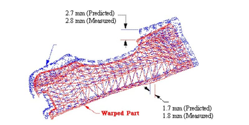
Figure 6. Measured and predicted final shape of a rear pick-up fender after shrinkage and warpage. The final part after de-molding is shown in red and the mold in blue.
During mold and part design for compression molding a great amount of the tedious trial-and error tasks are spent eliminating the sometimes unavoidable shrinkage and warpage. Predicting the final shape of the part after shrinkage and warpage is crucial for a complete CAE analysis of the process. The CAE software can be used to test the effect of various charge or gate locations, and different materials and processing conditions on the final shape of the part. Ideally the engineer can optimize the mold, material and conditions to obtain a part with the desired structural integrity and final shape in the computer before the mold is finalized.
Structural Analysis
After completing the mold filling, fiber orientation, and shrinkage and warpage analysis it is essential to simulate the structural behavior of the part. A structural analysis, or commonly called FEA analysis, simulates the mechanical performance and durability of the part during real operating conditions and loads. As explained earlier, the fiber orientation on different regions throughout the part results in anisotropic mechanical properties. Therefore, it is imperative to perform the structural analysis including the anisotropic material properties to complete the CAE analysis and obtain an optimized mold design and processing conditions.
Cost Savings Benefits of CAE
CAE tools when used properly provide enormous cost and time savings for part design and manufacturing. CAE allows engineers to virtually test how the part will be processed and how it will perform during its operating life. To exploit the cost benefits of CAE, the material supplier, designer, molder and manufacturer should apply these tools concurrently early in the design cycle.
Figure 7 shows a qualitative expense comparison associated with part design changes [9]. It is clearly seen that when design changes are done at an early stage on the computer the cost associated is on the order of 10,000 times lower than if the part is in production. Cost savings arise from avoiding mold modifications such as gate location and part thickness changes, production delays, scrap parts and machine set-up trial-and-errors.
At early design stages engineers and molders typically finalize part design based on their previous experience with similar parts. As parts become more complex it is harder to predict processing and part performance without the use of CAE tools. Even in the case of simpler parts the effects of processing, such as fiber orientation, can seriously change the structural capability of the product. The new trend is to use CAE tools to prevent the late and expensive problems that can arise during and after processing.
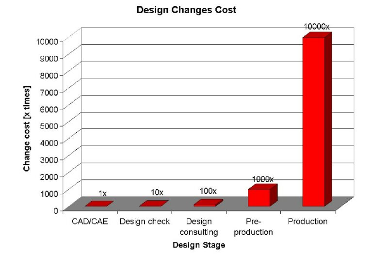
Figure 7. Qualitative cost of design changes during part design and manufacturing.
Case Studies
Ford Taurus Radiator Support
Figure 8 shows the model of a compression molded SMC radiator support for the Ford Taurus. This is a complex part where charge placement and molding conditions have a great influence on the mold filling and fiber orientation of the part. Here, CAE tools become very handy to model the manufacturing process and integrity of the part [10].
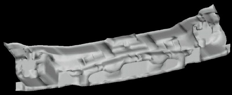
Figure 8. Solid model of Ford Taurus radiator support (courtesy of The Budd Company).
The main goal of the mold filling study was to avoid knitlines in areas of structural importance. The initial charge layout shown in Fig. 9 generates a knitline in the area highlighted with a circle. Here the knitline is located in an important structural area of the part. In order to change the location of the knitline a new charge layout need to be tested. With CAE tools it was easy to test different cases to optimize mold filling and avoid or relocate knitlines.
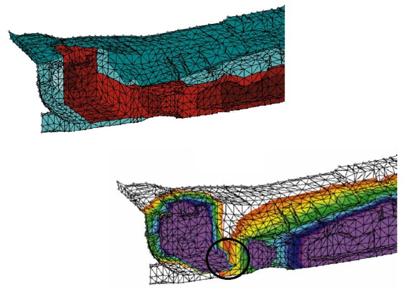
Figure 9. Initial charge layout (top) and mold filling (bottom) for radiator support – circle indicates knitline location.
After a couple of mold filling simulations a better charge layout, as shown in Fig 10, was found to eliminate the initial knitline. The optimized charge layout successfully leads to a much stronger part. Without the mold filling simulation it would have taken numerous trial-and-error moldings to achieve similar results in longer time.
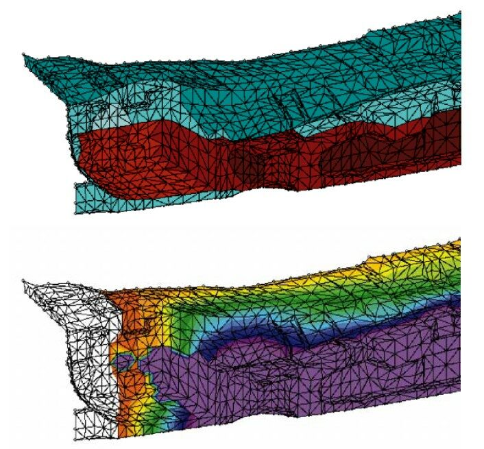
Figure 10. Optimized charge layout (top) and mold filling (bottom) for radiator support
Valve Cover
In this study a valve cover was initially compression molded using SMC. However, in order to increase production, it was desirable to switch the process over to injection-compression molding of BMC. The initial charge layout for the compression molding process, shown in Fig. 11, gives the location of the SMC charge. This charge location gave good filling results with acceptable fiber orientation distributions throughout the part.
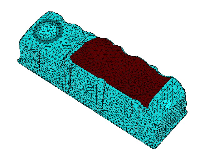
Figure 11. Valve cover with initial SMC charge location.
Initially, it was proposed to place the gate in the center of the region that was charged with SMC. It was thought that if the injection phase could transfer the BMC material into the cavity in roughly the same position as the SMC sheets were placed, similar fiber orientation and stiffness would be obtained. However, because of the rather thin region surrounding the oil fill knockout and the steep draft angles around the hole, a knitline was formed as shown in Fig. 12 [10]. The knitline formed on the downstream side of the oil fill hole due to the converging flow fronts flowing around the hole itself. Unfortunately, a knitline in this region compromised the structural integrity of the finished part and precluded this gating option as a viable manufacturing alternative.
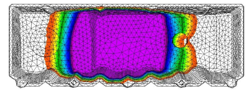
Figure 12. Mold filling of valve cover at the end of the injection phase showing a knitline.
In order to avoid the knitline around the oil fill hole, a second gating option was investigated. Here the gate was placed in the center of the oil fill hole itself. As shown in Fig. 13, the resulting flow field at the end of the injection phase avoids any knitlines. The initial injected material also closely resembles the SMC charge placement from Fig. 11.
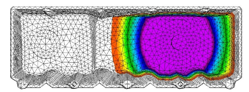
Figure 13. Mold filling of valve cover at the end of the injection phase for optimized gate location.
Accordingly, as shown in Fig. 14, the initial injection phase has also imparted a preferential fiber orientation distribution in the material. As the material flows outwards from the gate, the radial expansion flow from injection causes the fibers to orient themselves in a tangential direction. However, as the figure shows, this tangential orientation is made more complex by the geometric features of the valve cover.
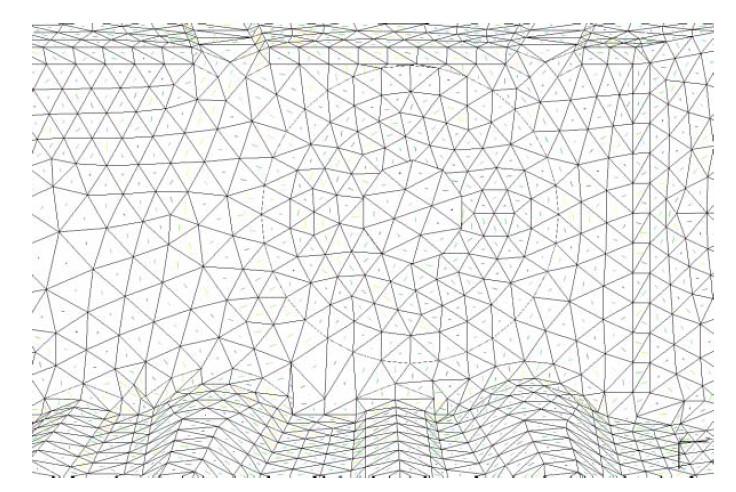
Figure 14. Fiber orientation of valve cover at the end of the injection phase for optimized gate location.
Finally, after the mold filling and fiber orientation have been fully calculated, the residual stress field during processing can be simulated. Upon de-molding this residual stress causes shrinkage and warpage as shown in Fig. 15. This figure shows a contour of the displacement field with a maximum deformation of 1.2 mm.
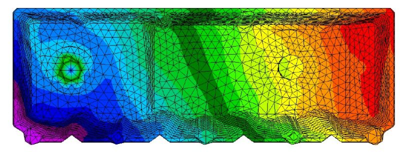
Figure 15. Shrinkage and warpage color contour of valve cover at the end of the injection phase for optimized gate location.
Conclusions
CAE tools allows for the simulation and optimization of the compression and injection/compression molding process to yield a good part design. Expenses of CAE analysis incurred at early design stages are quickly offset by the vast cost savings at later design stages.
With increasing requirements to decrease costs, improve quality, and reduce cycle time CAE is paramount for profitability. However, blind reliance on simulation should not categorically replace engineering and experience. Rather, CAE should continue to be used to solve processing problems as well as to help achieve the goal of designing “flawless” products.
References
1. Barone, M.R. and D.A. Caulk, “A Model for the Flow of a Chopped Reinforced Polymer Compound in Compression Molding, Journal of Applied Mechanics, p. 361, (1986)
2. Osswald, T.A., “Numerical Methods for Compression Mold Filling Simulation”, Ph.D. Thesis, Dept. of Mechanical Engineering, University of Illinois-Urbana Champaign, (1987)
3. Osswald, T.A. and C.L. Tucker, “Compression Mold Filling Simulation for Non-planar Parts Using the Finite Element/ Control Volume Approach”, International Polymer Processing, 5, 2, p.79, (1989)
4. B.A. Davis, R.P. Theriault, T.A. Osswald, “Optimization of the Compression (Injection/ Compression) Molding Process Using Numerical Simulation”, ASME Conference, (1997)
5. T.A. Osswald, E.M. Sun, S.C. Tseng, “Experimental Verification on Simulating Shrinkage and Warpage of Thin Compression Moulded SMC Parts”, Polymers & Polymer Composites, 2, 3, p. 187, (1994)
6. Folgar, F. and C.L. Tucker, “Orientation Behavior of Fibers in Concentrated Suspensions” Journal of Reinforced Plastic Composites, 3, p.98, (1984)
7. Osswald, T.A., E.M. Sun and S.C. Tseng, “Orientation and Warpage Prediction in Polymer Processing”, a chapter in Innovation in Polymer Processing: Molding, edited by J.F. Stevenson, Hanser, (1996)
8. Kamal, M.R. and S. Sourour, “Kinematics and Thermal Characterization of Thermoset Cure”, Polymer Engineering & Science, 13, 1, p59, (1973)
9. Bozzelli, J., “Scientific Injection Molding: The Plastics Point of View”, Seminar Notes, (2000)
10. Cadpress, Compression and Injection-Compression Molding Simulation Program, The Madison Group, Madison, WI