The success of manufacturing and assembling of plastic parts depends heavily on the design of the individual components. Each part must hold tolerance and be designed with the intent that it will function and assemble easily with other pieces. There are general plastic part design principles for a variety of manufacturing methods (e.g. extrusion, compression molding, blow molding, injection molding, casting, etc…). These different processes can have similar design principles, but when you start to account for secondary operations, such as ultrasonic welding, the principles guiding effective ultrasonic welding design become even more important.
This article will focus on the recommended ultrasonic welding design principles of injection molded parts that are to be joined by ultrasonic welding. This will also cover ultrasonic welding design and processing techniques to help ensure that a stable and robust welding process is established. These ultrasonic welding design guidelines and suggestions are meant to be taken qualitatively, as the design of different products may require unique approaches.
First Steps In Ultrasonic Welding Design
The first step in considering the ultrasonic welding of parts should be establishing what your requirements are. What material is best suited for the part application? Is this a material that is known to be easy to weld? Does the part design maintain a consistent wall thickness, a key aspect of good ultrasonic welding design? Is there an especially thick area that may have voids as a result of the molding process? Does a hermetic seal need to be created? What are the structural requirements of the final assembly? Do the number of weld sites create a strong enough part to satisfy structural requirements? Do the weld marks need to be hidden? These are just some considerations that design and manufacturing engineers absolutely must address before final part design, ensuring a solid foundation for the ultrasonic welding design, and mold construction.
Let us examine the ultrasonic welding process and how the adjoining components come together. Tight tolerances on the final welded component are not at all uncommon, especially in the automotive and medical industries. This means that when it comes time to weld the parts together, they should be fixed or aligned in a way that yields a consistent bond and final part orientation. A fixed orientation between the welded parts can be achieved with external fixtures, but proper ultrasonic welding design of the weld joint can also help to precisely control the part orientation at the bond. This aspect of ultrasonic welding design can be achieved with certain energy director designs such as a tongue and groove or through other locating features on the molded parts (pins and ribs).
Two general types of ultrasonic welding joint design include energy directors and shear joints. Energy directors were mentioned in the previous article, but let us re-visit them. An energy director, a key element in ultrasonic welding design, is a molded-in feature at the weld location on the part that helps facilitate the polymer in reaching a melt state. The energy director generally, is a small protrusion or profile that concentrates the energy directed into the part. These are often found on the part that makes contact with the horn. When this energy is directed into the smaller geometry, the resin reaches a melt state quicker than if the weld location only contained two flat faces (butt joint). Energy directors are more commonly designed for parts comprised of amorphous polymers, making their inclusion a frequent consideration in ultrasonic welding design for these materials. However they can also be used with some semi-crystalline resins. Figure 1 highlights a typical energy director design. Notice how the profile of the director comes to a sharp point. This tapering to a sharp point helps promote the concentration of energy and begins the melt process [1]. Included in Figure 1 are some general dimensional guidelines for typical energy directors used in ultrasonic welding design.
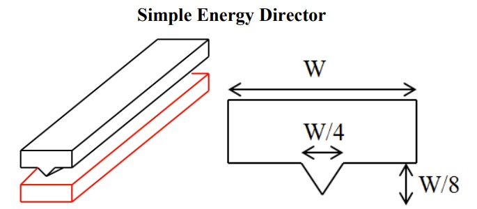
Figure 1: A simple energy director geometry, common in ultrasonic welding design. that follows a profile along the length of the weld area. [2]
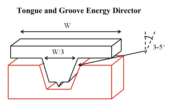
Figure 2: A tongue and groove energy director. These types of joints, employed in ultrasonic welding design, can be used to help with part alignment during welding. [2]
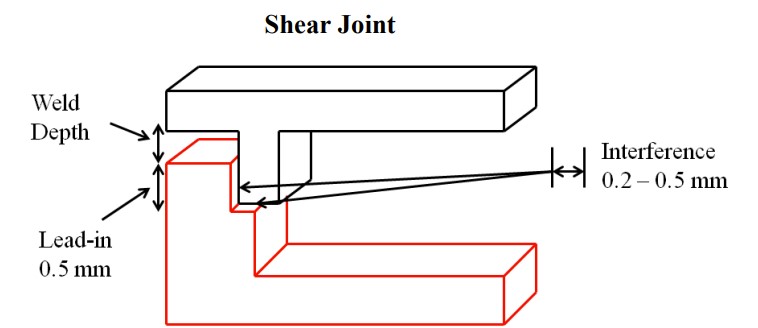
Figure 3: A typical shear joint used in ultrasonic welding. These case be useful for
creating hermetic seals. [2]
Widely accepted part design principles for injection molded parts can overlap with some of the ultrasonic welding design guidelines. Some of these guidelines can include consistent wall thickness, as well as having a radius added to all sharp corners. Some ultrasonic welding design suggestions, specifically related to the process, include a sufficient contact area for the horn of the welding machine, as well as sufficient material stiffness to be able to transfer energy to the weld joint.
Recall from the previous article that two generalized categories of ultrasonic welding include far field and near field welding. Near field welding indicates that the horn is up to 6 mm away from the weld joint, whereas far field welding is where the horn is greater than 6 mm away from the weld joint. It is preferred to have an ultrasonic welding process and overall ultrasonic welding design that incorporates near field welding. Proper ultrasonic welding design for near field welding helps ensure a wider processing window, and can reduce the likelihood of leaving visual marks on the part from the horn contact.
Let us take for example a nylon assembly where the design incorporates a simple tongue and groove energy director. It is determined that the part will be designed to undergo near field welding since the processing window for nylon is smaller than its amorphous counterparts. The weld joint area was designed to be one centimeter long. You quickly find out that this one centimeter weld section does not carry enough structural load for the entire assembly to pass testing standards. It is extremely beneficial to the mold builder that the size of this weld joint, as defined in the ultrasonic welding design, be incrementally increased. This prevents the scenario where the weld joint may be made too large and needs to be reduced. If this happens, steel will need to be welded back into the mold and re-machined, which is very time consuming and expensive.
Environmental Considerations for Ultrasonic Welding Design Success
Next, you find that the weld joint is failing under the structural load, even though the joint size was increased as per an adjusted ultrasonic welding design. When you inspect failed parts, you notice that there are porous sections of polymer along the weld interface that may be contributing to premature failure. After inspecting the welding process, it is discovered that the parts being welded have been sitting in inventory for a week before being welded. Due to the extremely hygroscopic nature of polyamides, these parts that have been sitting in inventory have become conditioned to the environment and absorbed approximately 2.5% water by part weight from the air. The water content in the nylon attempts to work itself out of the system in the form of bubbles and voids during the welding process, undermining the intended design. Therefore, it is beneficial to ultrasonically weld these parts dry-as molded to avoid porosity and void formation.
These are general ultrasonic welding design guidelines. Considering the design, material, as well as the required processing before mold creation, is crucial. Each case will be different and will present its own challenges. While keeping these suggestions for ultrasonic welding design in mind, a robust process can be developed that will result in a consistent product.
References [1] Grewell, Benatar, Park, “Plastics and Composites Welding Handbook”, (2003). [2] Rotheiser, “Joining of Plastics”, (2009)
This article was originally published by Patrick Mabry, M.S.