The increasing push to integrate light-weight materials into performance demanding applications has made plastics a material of choice for designers. Additionally, once a product has been converted to plastic, the desire to further minimize material and weight without sacrificing performance typically follows. These two trends of light-weighting and reducing material consumption have led many designers to ask the questions “How much material can be removed?” and “What should my wall thickness be?” The answer to both of these questions should start by revisiting the first rule of plastic part design. That rule states that every plastic part should maintain and establish a uniform nominal wall.
Establishing the nominal wall of a part is one of the more mundane details of product design, but it is also one of the most critical. The nominal wall establishes the overall size and dimensions of the part. The nominal wall will also dictate many decisions regarding the design and spacing of more interesting features such as stiffening ribs, louvers, mounting bosses, and snap-fit design. None of these features can operate optimally without establishing the correct nominal wall of the part.
What should the nominal wall be?
The preliminary decision of establishing a nominal wall should be dictated by the functional performance requirements of the part. Considerations of acceptable stress levels, and expected lifetime of the part should help guide the designer in establishing the nominal wall. Previous experience and the correct interpretation of structural finite element analysis (FEA) has made these decisions more reasonably attained during the preliminary design stages.
While performance dictates the minimum nominal wall of the part, manufacturing should also be considered. The designer must remember that injection molding is a pressure driven process. Thinner walls and longer flow lengths will require higher injection pressures to fill the mold. Most modern conventional injection molding equipment can achieve between 20,000-30,000 psi of plastic injection pressure. Specialized micro -molding machines can achieve higher pressures, but have other limitations such as shot size.
Injection molding simulation can be used to determine the feasibility of manufacturing a part at a given wall thickness. Figure 1 shows a graph of required injection pressure to fill a plastic shroud vs. the nominal wall thickness. During the preliminary design stages, the product designer determined the minimum wall thickness of the shroud to withstand the intended loads was 1.5 mm. However, a series of studies that simulated the injection molding process revealed that the part would require too high of injection pressures to fill at 1.5 mm, and the processing window would be small. The simulation also helped the designer determine that from a manufacturing perspective, the minimum wall thickness was 2.25 mm.
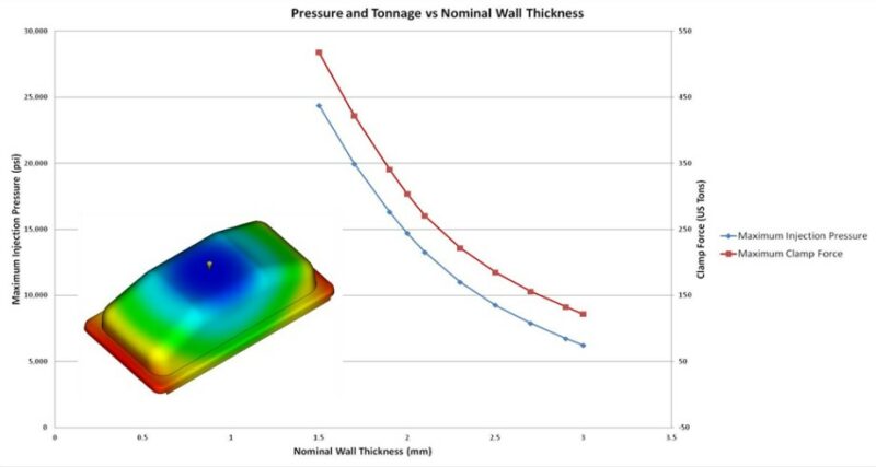
Figure 1: Graph showing the predicted injection pressure vs. nominal wall thickness for a plastic shroud. The analysis showed that the minimum wall thickness to maintain a reasonable injection pressure was 2.25 mm.
Why is it important to maintain a uniform wall thickness?
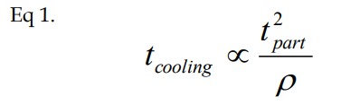
Once the nominal wall thickness is established, it is important that the wall thickness remain constant. Maintaining a uniform thickness will allow for the best possible processing of the part, and will minimize any residual stress in the part. Plastics are inherently poor heat conductors. By maintaining a uniform wall thickness, the part will cool as uniformly as possible. This also means, if packed properly, that the part should shrink as uniformly as possible. Equation 1 shows that the cooling time of a plastic part is directly proportional to the square of the wall thickness.
 This means that with a 2 mm wall, the part will take 1.76 seconds to cool, but a 4 mm wall will take 8.00 seconds to cool. If these two wall sections are placed adjacent to one another, the 4 mm wall will want to shrink significantly more than the 2 mm wall, Figure 2. As a result of this differential shrinkage, a stress develops that the part will want to relieve upon ejection, which results in part warpage. If the part design requires certain areas to act stiffer than others, there are better options than simply thickening up the wall. The addition of ribs or profiling the part wall to achieve a stiffer part while maintaining the uniform wall thickness will allow for more success than selectively increasing the part wall thickness.
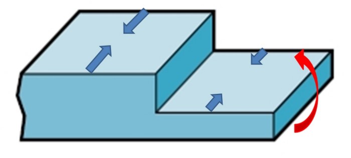
Figure 2: Schematic shows that varying the wall will result in differential shrinkage and excessive warpage of the part.
Plastics are a versatile material that allow a designer many advantages and freedoms. However, the designer must take a holistic view of the plastic part design and consider not only performance but also manufacturing during the design stage. Considering manufacturing and remembering to maintain and establish a nominal wall thickness will allow the most success in creating a high quality product.