To successfully design and manufacture a plastic component requires collaboration between a diverse team of designers, manufacturing engineers, material experts, and tooling engineers. Oftentimes when it is required to mass-produce complex, dimensionally stable parts, the team will turn to injection molding for their process of choice. While the team is critical for designing the feature, performance requirements, and tolerances, it comes down to the molders and toolmakers to determine how to fit all these desired features and performance criteria into a mold. Additionally, while significant time and resources are dedicated to getting the design of the part correct, it is usually a mad dash to get the mold designed and manufactured so the product can make it to the consumer. With the competitive global landscape for manufacturing, the need to quickly make decisions to get first-time right parts is critical. Many molders and toolmakers have turned to injection molding simulation to experiment with or “prove out” their mold designs, Figure 1.
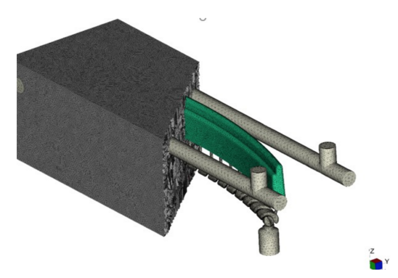
Figure 1. Injection molding simulation can model the entire mold design.
However, the question of “How accurate is the simulation?”, often comes up. To help move this question forward, we will be writing a five-part series to help provide clarity on how simulation can best be utilized, and move the simulation activity from a check-the-box step to an optimization step that will in the end, reduce the cost and lead time for getting first parts. In this installment considerations for optimizing our mold filling and packing parameters, and how it might influence our runner and gate design, will be addressed.
One of the first decisions for optimizing the filling process for injection molding is selecting the best gate location(s) to start forming the part. There have been numerous articles and books written about selecting the gate location. Additionally, many times the part designer puts restrictions on the gate location or amount of vestige that will force us to put the gate in a non-ideal location. Therefore, this article is going to discuss how we can move forward with replicating the mold performance after the gate location has been selected.
Step I: Define the Analysis Objective
As with any tool, an analyst or designer should start any simulation project with defining the objective of the analysis. While simulation can simulate almost all stages of the injection molding process, it is not always necessary to simulate the entire mold design or have a finalized mold design to effectively utilize this tool. By defining the objective, the analyst can better define how much of the mold design is required to be defined. For mold filling, the objective of the analysis is to fill the mold, and be able to pack out the part to avoid issues like excessive sink without requiring excessive pressure. Therefore, to start creating a digital twin of how your mold will perform or how it is performing, the minimum requirement is to model in the parts and feed systems. While the feed system may never be seen by the customer or consumer, it will definitely influence factors like pressure to fill the mold, weld line location, and even dimension stability of the part.
Step II: Define Your Metrics
Step II of creating your digital twin highlights one of the major issues within the plastics industry, and that is oftentimes the team we assemble to design and optimize our plastic part manufacturing, are not speaking the same language. In this case, language is not the tongues they speak, but rather it refers to the terminology the team members use. This disconnect in communication is also a common problem with transferring simulation results to the process development team. So, when it comes to determining how accurate a simulation is, it is critical to determine how we are measuring and defining our measurement metrics. As an example of this miscommunication, we look at the term, “gate seal.” For most professionals within injection molding, this term refers to the time it takes for the gate to freeze off and prevent additional material from being injected into the mold cavity. However, a simulation analyst is often taught to use factors such as the frozen layer fraction to help determine when the gate freezes off. When the frozen layer fraction reaches 100%, that means that the entire crosssection of the gate has frozen, and no more material can be injected into the mold. Currently, there is not a commercial way for a process engineer to measure the frozen layer fraction at the gate. Rather, they use the measured part’s weight vs. packing time to determine when the gate seal is achieved. Therefore, we are using different systems to measure this point in the process.
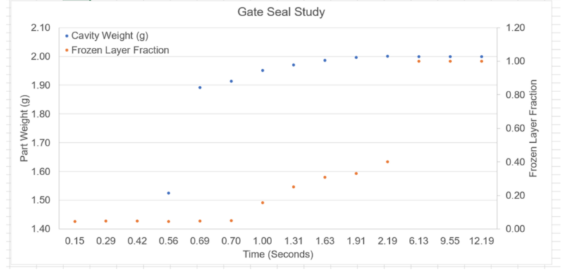
Figure 2: Graph shows that using different systems to determine the gate seal, can lead to different conclusions.
As Figure 2 shows, if these two different systems are plotted against one another, we come to two different conclusions for the gate seal time. This discrepancy does not indicate which system is right, but rather is an artifact of the inability to measure the same parameters. Therefore, we should not expect that we will always come to the same conclusion in every scenario. Additionally, it does not mean that analysts should not adjust their findings/ decision criteria to better guide the team and correlate their results to reality. A study should be done to determine which is more representative.
With the initial mold filling parameters, oftentimes fill time and transfer position are the critical parameters identified to characterize the process. However, again, many times the exact fill time and transfer positions are determined by different system metrics. The analyst may use injection pressure to fill, melt temperature variation at the flow front, shear rates through the gate, and frozen layer fraction to determine the fill time. Yet, a process engineer will use a “rheology curve,” linearity study, part weight at transfer, and part cosmetics to help determine the fill time. Therefore, it can be difficult to determine the correlation since we are using different criteria. Still looking at the two different systems to evaluate the fill time, it is interesting to see that they can lead to very similar conclusions. Table 1 shows a comparison of the fill time determination for a thin-walled polypropylene cap from a simulation and from a scientific molding fill study. Comparing the results suggest that the results are very comparable. Therefore, despite having different evaluation criteria, the two approaches can still come together to the “same” answer.
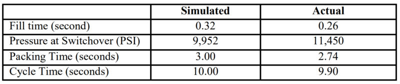
Table 1: A comparison of the fill and pack results between simulation and actual measured, showing good correlation.
Step III: Acquire the Appropriate Inputs
Once the objective of the study has been established and the critical metrics are defined, it is important to ensure the appropriate simulation inputs are provided. It is an almost overused phrase of “garbage-in, garbage-out,” but it is a very valid point. If the objective is to create a digital twin of our physical mold and process, it is important to make sure we are “asking” the digital mold to perform the same tasks as the real mold. This means we need to make sure our boundary conditions or inputs of the simulation, are similar to those we are subjecting on the physical mold.
Probably the most important input is to ensure the plastic material that we are actually molding with is characterized for our mold filling simulation. It is important that an analyst tries to gather as much measured data for the physical resin and develop the appropriate flow models. Simply finding a similar melt flow rate material in the same family, with similar fillers, is not acceptable. The boundary conditions of the melt flow rate test are not representative of those conditions experienced during injection molding. Injection molding often focuses on the shear behavior of thermoplastic materials, due to the shear thinning behavior of the material. This material behavior is one reason why injection molding generally uses faster fill speeds. As the material experiences more shear, the viscosity of the resin tends to decrease, Figure 3.
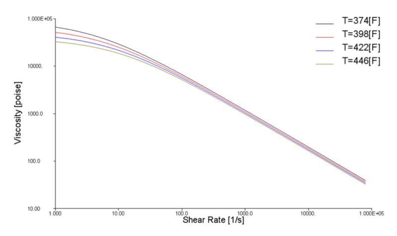
Figure 3: Plot showing how viscosity changes with increasing shear rates.
However, shear deformation is only one of the deformation modes experienced in injection molding. There are also extensional deformation forces, where the material is stretched as it flows through changes in the cross-sections in the mold. These restrictions in flow often occur in the feed system in the mold, especially at the gate. So when a hot manifold system, tunnel gate, or pin gate is used to fill the cavity, it is important that we have a material that has this extensional viscosity characterized. Figure 4 shows a comparison of an injection pressure curve during the initial mold filling stages, when the resin is characterized for shear and extensional viscosity, and when it is only characterized for shear viscosity. The difference is very clear. There is an under-prediction of pressure to fill the mold when the extensional viscosity is ignored. The cost and time investments to characterize the extensional viscosity are minimal and can have a substantial influence on the design decisions that are made during the early-stage mold development process. Adjusting the mold design and allowing for a larger process window for the process engineer without needed modifications to the physical mold, easily justifies the time and financial investments.
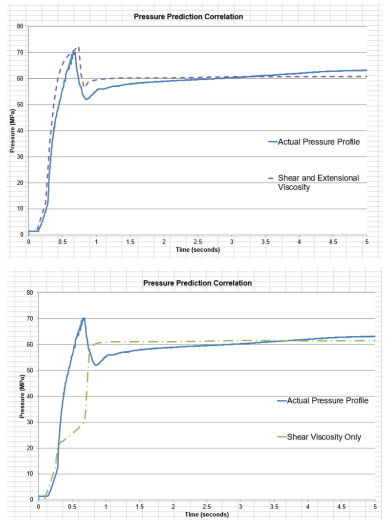
Figure 4: Graphs highlighting the importance of accounting for shear and extensional viscosity to accurately predict pressure to fill the mold.
From a modeling-of-the-physical-mold perspective, to properly modeling the behavior of the melt during the initial mold filling stages, it is critical to have the feed system and mold cavities included in the model. The feed system design should be designed to impart shear on the molten plastic that will heat the material up and allow for a lower viscosity in the mold cavity. However, this additional flow length and the characteristic cross-section of the feed system will add additional pressure loss during the mold filling process. If the feed system (runner and gates) is not included, any attempt at comparing pressures at the press to those simulated, are a waste of time since we are not measuring the pressure at the same locations. While this seems like an obvious statement, such a detail is often lost when comparing simulation to real life, and can raise concerns of the fidelity of the simulation results. Finally, the last inputs that are critical for achieving high fidelity results are to ensure representative “plastic conditions” are used for setting the filling simulation. Ensuring a representative melt temperature and mold temperature are used for the simulation, as well as the proper flow rate of the polymer into the mold, are critical for properly capturing the shear and thermal conditions the resin experiences during the mold filling stage. As Figure 4 shows, when those conditions are properly modeled, not only can the maximum pressure to fill the mold be captured, but the entire injection pressure profile can be captured with good correlation during the entire mold filling stage.
Step IV: Close the Loop and Correlate
The last step of creating a digital twin of your mold is to close the loop. Too often, simulation is viewed as an early development process step and once the simulation step is complete, the report is filed away and never to be seen by the process engineer. However, this is doing a disservice to the investment that was initially made by performing the simulation. By not sharing the simulation results with a process engineer, extra steps and time is required at the press to reestablish parameters that were already determined to be successful. Now, it is not to say that the process should be set up to match the simulation. However, the simulated results can help a process engineer narrow their initial scope and potentially find solutions to other issues that developed that were not initially defined in the simulation scope. Despite all the advances in in-mold sensors for injection molding , there is still limited information that a process engineer can gather to help t h e m troubleshoot a process. Generally speaking, a process engineer will only have one-to-two physical sensors in the mold cavity to help them generate data. However, in a simulation there are thousands to millions of virtual sensors that can give the process engineer more information to quickly troubleshoot a process. Whether that is looking at cosmetic defects at the gate, end-of-fill, or difficulty packing out the part. The simulation results allow for an opportunity to empower the process engineer and provide them with more information to troubleshoot those issues. Additionally, the analyst can gain valuable feedback on what additional issues arose to start developing a more robust cosmetic process window for the part as well, Figure 5. The simulation should be an additional tool for the process engineer to further confirm their experience and intuition and help find solutions more quickly.
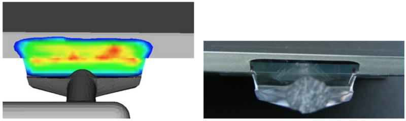
Figure 5: By closing the loop and providing process engineers simulation results even cosmetic defects can be predicted with simulation.