In Part 1 of this series, we explored how to effectively utilize injection molding simulation by focusing on accurate inputs, clearly defined objectives, and collaborative communication. Now, you might be thinking that extensive upfront work and a complete mold design are necessary to obtain mold filling system optimization. However, this isn’t always the case. In fact, the most common objectives of injection molding simulation often boil down to two fundamental questions: “Can I fill my part?” and “What is my cycle time?” These questions are crucial because they directly impact mold yield and part cost. This installment will demonstrate how the “Keep It Simple Stupid” (KISS) principle can help us quickly answer these questions, even without a fully finalized mold design. We’ll explore the essential elements needed to obtain mold filling system optimization and achieve efficient cycle times, enabling you to leverage simulation for early-stage decision-making and cost-effective part production.
What Do I Need in my Simulation Model
In order to start answering the questions about the ability to fill your part and what the cycle time may be, you need at least three items.
- Your specific plastic material
- Your part design
- Your feed system
Material
The integrity and fidelity of the material data you use in your simulation is critical, as we highlighted in our first installment of this series. Luckily many of the commercial software companies and resin suppliers have partnered to create public databases where you have access to this data when you purchase the software. Autodesk Moldflow, specifically, has over 10,000 grade specific resins characterized for their software. Therefore, there is a good chance that your resin will be characterized already. It is always good to vet your data, but that highlights the importance of closing the loop in the end.
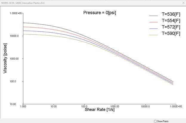
Figure 1: Having good material data is critical for obtaining high fidelity mold filling simulation results.
Part Design
Having a good representation of your part design is also critical. With today’s 3D modeling capabilities, it is relatively easy to get a good representation of the part design. The important aspects to have properly captured in your part design are the overall part dimensions, and the part thickness. Since injection molding is a pressure-driven process, the thickness distribution of the part will dictate how the polymer flows through the cavity. It will also dictate the weld line locations, air traps, and fiber/molecular orientation in the part. Therefore, gating is critical for optimizing the mechanical strength of your component.
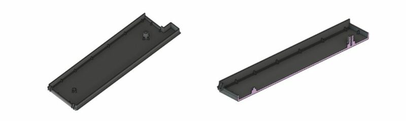
Figure 2: Ensuring the geometry properly represents the part thickness and includes all critical features is important for simulation success.
Feed System
The feed system (runner system) is the last aspect that is critical to help determine cycle time and the feasibility of filling the part. A big driver for mold and part cost is how the material will be conveyed from the injection unit to your cavity. Whether the direction is to use a hot runner, cold runner or a combination of the two, simulation can easily represent the feed system in your study. Inclusion of the feed system is critical, because it will influence the total flow length the molten plastic material needs to travel in order to fill the cavity, and will therefore increase your injection pressure to fill the mold. Occasionally, the feed system dimensions will be non-optimal and may even result in a larger pressure drop than your cavity. Addressing runner sizing during simulation can help minimize mold rework, and project delays by identifying those issues up front.
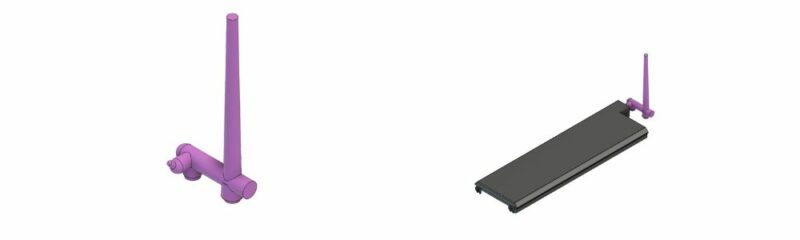
Figure 3: Including the feed system into the model is critical for obtaining accurate injection pressures and cycle times.
Finally, including the feed system, particularly a cold-runner feed system, is critical because the cross-sections of the runner are often larger than the part wall thickness. Therefore, they will take a longer period of time to cool and will require a longer cycle time than the part alone. Figure 4, highlights that the design of the feed system will require twice the cooling time of the part alone. Therefore, by including the feed system in your model, you can get a more accurate idea of the material consumption and the overall cycle time for the part during your quoting stage.
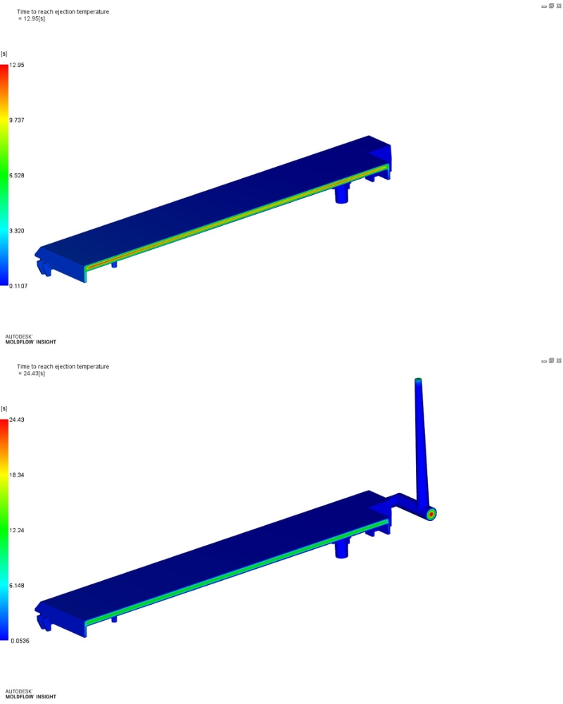
Figure 4: The images highlight that the feed system will often dictate the cycle time for a given mold, which may influence the overall part cost.
Using the KISS Principle for Feed System and Part Modeling During Mold Filling
With the proper geometric and material inputs gathered for the simulation to be performed, the next question is how to properly model the feed system and part. Depending on the simulation package being used there are options of generating a model using triangular elements, tetrahedral or brick elements, or even voxels! With the rise of computational power available to engineers and designers and the perception that full 3D meshes are more accurate, many analysts assume that meshing both the part and the feed system with full 3D elements will yield the best results, particularly for pressure predictions. However, I have found that as long as the overall flow length, and flow channel thickness is properly captured using the simpler beam or triangular meshes can yield more accurate injection pressure predictions.
The tables and graphs below show how the plaque geometry and feed system models shown in Figure 2 could be represented with different meshing strategies, and how the predicted pressures to fill the mold compared to reality.
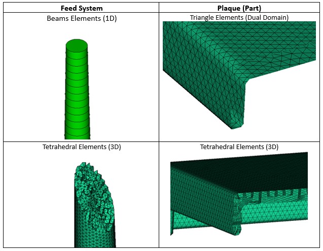
Figure 5: Images highlight the different elements that could be used for the feed system and plaque geometries.
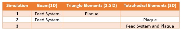
Table 2: Description of the different types of elements used to represent various meshing strategies.
The graphs in Figure 6 highlight that using the simpler modeling method allows for similar, if not more representative, injection pressures and that all appear to correlate well with the actual molding process. Using the simpler elements also helped decrease the solve time and would allow for more flexibility changing dimensions of the part without having to go back to a part designer or customer.
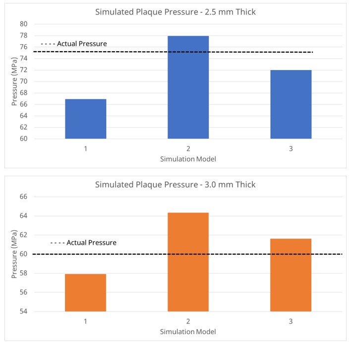
Figure 6: Graphs compare actual pressure vs simulated pressures for plaques at different thicknesses with different mesh elements.
In conclusion, achieving mold filling system optimization doesn’t necessarily require a complete mold design or extensive upfront effort. By adhering to the KISS principle and focusing on the essential elements—accurate material data, a representative part design, and a well-defined feed system—you can effectively leverage injection molding simulation for early-stage analysis and decision-making. Even with simplified models, simulation can provide valuable insights into fill time, cycle time, and potential pressure limitations, enabling you to optimize runner and gate design, minimize mold rework, and ultimately reduce costs. By embracing simulation early and often, you can streamline the injection molding process, improve part quality, and accelerate time to market.