This article was originally authored by Ross Jones.
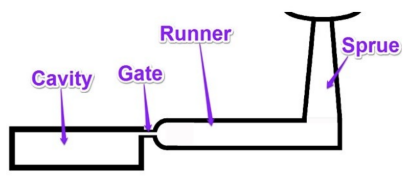
Figure 1: Schematic of a feed system for a conventional two-plate tool.
The feed system of an injection mold is responsible for transporting molten plastic material from the machine nozzle to the mold cavity. Figure 1 shows a typical cold runner feed system for a conventional two-plate tool. The feed system consists of a sprue, runner, and gate. Improper sizing of this feed system can lead to:
- Cosmetic defects (splay, sink, color variation, burning)
- Reduced material properties
- Excessive part cost
- Narrow processing windows
Properly sizing the feed system for an injection molded part is not only critical to reducing part cost but crucial for manufacturing high quality parts.
Sizing the gate:
The gate is the transition zone between the runner and the part cavity. The primary goals when optimizing gate size are maximizing control over the packing stage, avoiding excessive pressure drop, and maintaining acceptable shear rates. The larger the gate size, the longer the packing stage and the lower the pressure required to fill the mold.
The injection gate is typically the region of the feed system with the smallest cross-sectional area. As a result, the gate is usually where the plastic material experiences the highest shear rate. Shear rates experienced by the material are a function of injection speed and cross-sectional area, Equation 1.
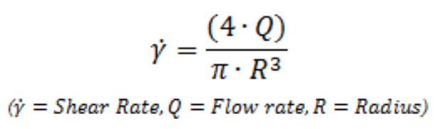
Equation 1. Shear rate through a circular cross-section for a Newtonian fluid.
In the shear rate equation, the cross-sectional area of the flow path is has an exponential relationship to the amount of shear the material experiences (for a circular cross-section, the radius is cubed). Therefore, a small change in the radius or thickness of the gate will have a dramatic effect on shear rate.
Amorphous (PC, PMMA, etc.), fiber reinforced, and heavily filled resins are typically more shear-sensitive materials. Therefore, they require larger gate sizes to reduce temperature rise and pressure requirements. As a general rule, the gate size for a fiber-filled resin should be 10% larger than an unfilled resin. Reducing shear on the material is vital to minimizing fiber damage during injection. Unfilled semi-crystalline materials are typically less sensitive to shear than amorphous and fiber reinforced materials. This allows for smaller gate sizes and higher shear rates.
Figure 2 displays a commonly used gate style known as the “tunnel” or “sub” gate. This gate style allows for automatic degating during part ejection and avoids a secondary gate removal process. Tunnel gates are typically sized to be 50-80% of the wall they are located on to ensure breakage at the gate and avoid excessive wear on the mold. Reducing the gate size will reduce the length of the pack stage. However, a shorter packing stage can lead to high shrinkage, voids, sink, and warp.
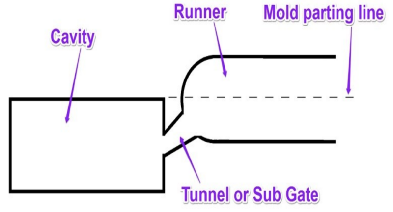
Figure 2: Schematic of a typical tunnel or sub gate.
Figure 3 displays another commonly used gate style known as the “edge” gate. This gate style requires a secondary gate removal operation. When necessary, the edge gate design allows for larger gate sizes and more control over the packing stage. Additionally, edge gates help maintain lower shear rates and injection pressures. Similar to tunnel gates, edge gates are typically 50-80% of the injected wall thickness.
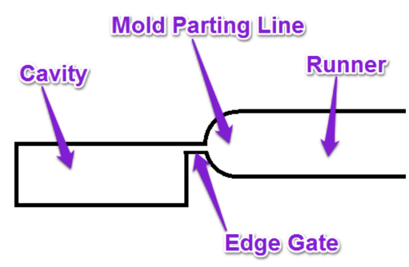
Figure 3: Schematic of a typical edge gate.
Sizing the runner:
The runners in a mold are the flow channels that connect the injection unit or nozzle to the injection gate, see Figure 1. The primary goal for optimizing a runner system is to achieve a balanced fill pattern for all cavities. Proper sizing of the runner balances the benefit of shear heating in the resin with the increased pressure requirement to fill the runner. An optimized runner will allow the molten plastic to increase in temperature improving flowability while not requiring excessive pressures to fill. Ideally, the pressure requirement to fill the runner should be less than 25% of the pressure to fill the mold. However, practicality and cost considerations often make this a difficult parameter to meet.
Proper runner sizing is dependent on material morphology and part thickness. Similar to gate sizing, amorphous materials require larger runners to reduce pressure requirements and temperature rise, whereas semi-crystalline materials can utilize smaller runner sizes.
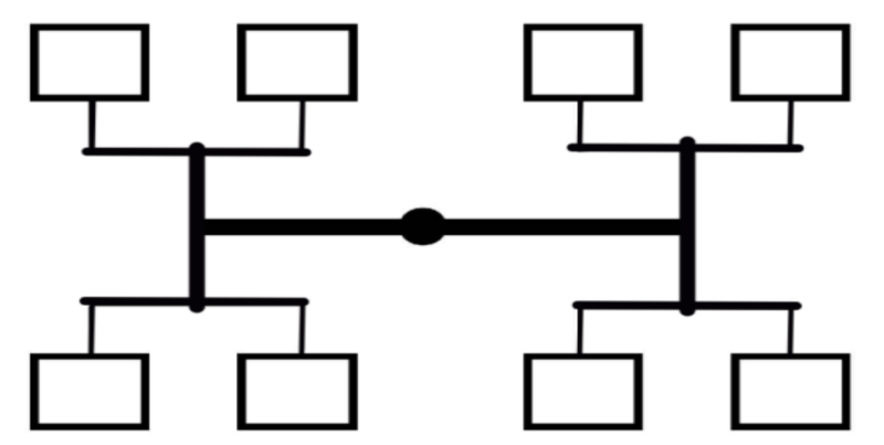
Figure 4: Schematic representation of a naturally balanced feed system.
When designing for a multi-cavity tool it is critical to fill all the cavities at the same time to manufacture consistent parts. Many multi-cavity molds utilize a naturally balanced runner layout where the flow distance is the same to each cavity, Figure 4. When designing the feed system each runner/branch should progressively decrease in size the closer to the injection gate. The smallest runner section should not freeze off before the injection gate. This will help prevent excessive pressure requirements, temperature rise, and material degradation due to an undersized runner.
Properly sizing the gate and runners in a feed system is critical to reducing processing requirements, increasing manufacturability, and reducing part cost. Utilizing injection molding simulation can be a cost effective tool for optimizing the runner and gate sizing of injection molded parts.
To learn more about gate and runner sizing and optimization, check out these videos: