In an era where innovation, lead times, and speed to market are critical to the successful launch of a product, any advantage is desirable. At The Madison group, we pride ourselves in our knowledge and understanding of everything plastics from formulation, processing, product life cycle, to failure analysis. We work to provide those advantages for you to reach your path critical goals. This article covers assembly processing of plastics via ultrasonic welding. It is intended to be an overview of the process, with future, more in-depth articles to follow.
There is no shortage of assembly methods when it comes to plastics. However, depending on the application, certain assembly methods will be more effective at helping ensure the longevity of the bond in the designed parts. Ultrasonic welding is an extremely popular process for joining plastics. Similar to most assembly methods, ultrasonic welding has positives and negatives. This process is mainly selected due to the following:
- Fast Cycle Times
- Ease of Automation
- Clean Process
- Localized Operations
A wide range of polymers can be welded, but there are some restrictions in terms of which different ones can be welded together. Generally, stiffer materials provide a better medium for the welding process, including some fiber filled material. It is important to note that stiffer materials must also be able to provide an adequate amount of viscous heating to effectively weld polymers.
So how does it work? Ultrasonic welding bonds two plastics (similar or dissimilar polymers) via concentrated ultrasonic motion. A transducer translates electrical energy input into physical motion. The overall physical distance traveled in one stroke of this motion, is the amplitude of the process. A typical amplitude range for ultrasonic welding is 10-250 µm. This motion can be amplified through a booster if higher frequencies are required to weld the polymers. The ultrasonic motion is then concentrated again through a horn. The horn is what contacts and delivers the ultrasonic motion to the material and begins the welding process. This is shown below in Figure 1.
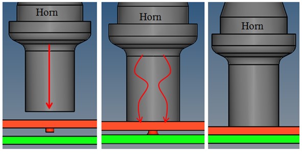
Figure 1: A horn makes contact with two materials. The energy director promotes the start of the polymer melt at the weld interface.
The cyclical energy is converted into heat, within the thermoplastic polymer, through intermolecular friction [1]. At the weld interface, polymer chains from both parts of the assembly become diffused and entangled once they have reached a melt state. When the welding process is complete, the resulting part should have a strong, clean, and predictable bond between the materials. This process is highlighted in Figure 2. The time for the part to cool down from the welding process is extremely short, because the heating of the materials at the weld interface is highly localized.
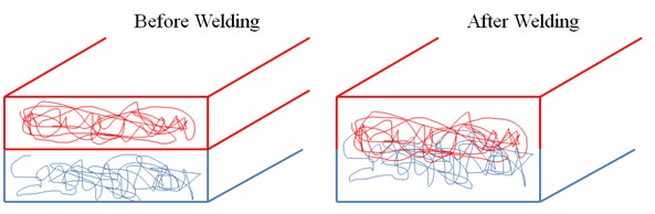
Figure 2: Molecular interface before and after the welding process.
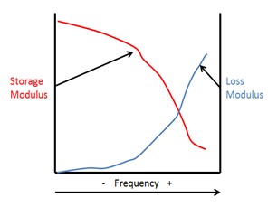
Figure 3: In general, most polymers will see a decrease in storage modulus and an increase in loss modulus as the testing frequency increases.
Let Us Talk Physics: The driving physics behind the ultrasonic welding process can be explained in terms of material properties and dynamics. The amount of heat generation at the weld interface is directly proportional to the loss modulus of the material. The heat generation is also dependent upon the frequency of vibration and strain amplitude of the process [2]. The loss modulus is the amount of energy a material will dissipate as heat from dynamic input. Its value can change based upon testing conditions such as temperature, strain amplitude, and frequency. This material response can be measured with Dynamic Mechanical Analysis (DMA). Characterizing the loss modulus via DMA is done with a frequency sweep analysis. An example of this type of analysis is shown in Figure 3. The sample is oscillated from lower to higher frequencies and the material response is recorded. As the frequency increases, the polymer has less time to recover the stress input, and begins to dissipate the input energy as heat. Some DMA analysis can be performed to predict the dynamic material behavior at higher frequencies. This is done by time-temperature superposition analysis [1].
The loss modulus is one of the few material behavior factors in determining the amount of viscous heating, and may be a good way to characterize whether a material is suitable for specific ultrasonic welding processes or not. A robust ultrasonic welding process will produce enough heat generation to drive the weld interface to a melt state. Typical frequencies used in ultrasonic welding range from 20-40 kHz, and the process can be limited by several different factors (Time, power, distance, force, etc…).
Are these two polymers weld-compatible? For example, polycarbonate is a widely used material for ultrasonic welding due to it being amorphous and relatively stiff. Amorphous polymers require less energy to weld than semi-crystalline polymers. A quick way of determining polymer compatibility is to check the melt flow rate (MFR) of a material. This should give a good indication of how quickly each material can reach the melt state during the welding process
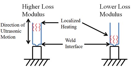
Figure 4: Behavior of a high loss modulus polymer as compared to low loss modulus. An appropriate blend of loss modulus and welding frequency is required to place the localized heating from the welding process at the interface of the polymers.
Are the materials that are being welded too soft? Recall, the appropriate material choice for the ultrasonic welding process should be relatively stiff. The material must also be able to translate the ultrasonic motion from the horn to the weld interface by viscous dissipation. A material that is both stiff and can dissipate the energy through the part will ensure that the assembly being welded can generate heat at the weld interface.
Some materials may have a naturally higher loss modulus, and may dissipate energy locally, but not through the part. Not being able to effectively translate the energy through the part, may result in a poor weld interface. This phenomenon can be seen in Figure 4. The higher loss modulus material will heat up at the point of contact with the horn, whereas the lower loss modulus material will translate the ultrasonic motion and energy to the weld interface and begin to heat up there. Adding a filler material, such as glass fiber, may stiffen the polymer enough to better transfer energy and create a quality bond interface. It is also important to know if the material needs to be dried prior to welding. For example, polyamides are very hygroscopic. Because the moisture will effectively reduce the stiffness of the polyamide, they generally need to be dried before welding.
Does the part design allow for ease of welding? Part geometry is a critical aspect of ultrasonic welding. The horn must be able to easily contact the parts being welded together. If the area is limited where the horn can contact the material, inconsistencies in the process may occur. Limited areas of horn contact can also make the part difficult to fixture securely. Near field welding should be used whenever possible, and should be taken into consideration when designing the parts for assembly. Near field indicates that the horn contacts the material at or less than 6 mm away from the welding interface. Wall thicknesses should also be a primary design consideration when investigating the use of ultrasonic welding. If a wall thickness used in the welding process is too thin, it may yield inconsistent bonds from part-to-part because of its ability to effectively transfer the ultrasonic motion.
Another key design concern is accounting for residual stress. If the two parts being welded need to be deformed in order to make contact, the magnitude of the force related to that deformation will be contained by the weld. Over time, a weld that contains residual stresses may fail due to creep. For example, take a thin walled cylinder such as a plastic drinking straw. If the end of the cylinder needs to be welded flat to create a hermetic seal, the plastic must deform to meet its new shape. The stress associated with that deformation will be stored at the weld interface and carried by the polymer bond. If the product is susceptible to creep, the cylinder may begin to fail and open at the weld location. Environmental conditions will also play a role in the strength of a weld which contains residual stresses.
Are there sharp radii in the part design that could break during welding? Sharp radii can result in part damage or full breaks at their location in the part once the ultrasonic motion is translated into it. A smaller radius promotes a larger stress concentration in the geometry, as compared to a smoother radius. Low strain-to-failure materials may be susceptible to this.
What kind of equipment is right for the project? The level of sophistication that is integrated into ultrasonic welding equipment has grown significantly, as it has become more popular in manufacturing settings. Molded part assemblies that maintain strict dimensional tolerances (medical and automotive) may often require welding equipment that has built-in quality and statistical process control (SPC) software. Ultrasonic processes such as spot welding may not require such advanced equipment. It is also important to understand the operating frequencies that the process will require. Typical welding machines have an operational range from 20-40 khz, but specialty machines can range from 10-70 khz.
These are general guidelines for product development for the intended use of ultrasonic welding. Each case will be different and present its own challenges. While keeping these suggestions in mind, a robust process can be developed that will result in a consistent product.
References:
[1] Grewell, Benatar, Park, “Plastics and Composites Welding Handbook”, (2003).
[2] Marcus, Miranda, “Ultrasonic and Spin Welding” (2014).
This paper was originally authored by Patrick Mabry and Paul Gramann, Ph.D.