Today’s topic is a very interesting one where we will be looking at a component of a household appliance that failed directly as a result of poor design mistakes that could have been easily prevented.

Figure 1: Over-the-range microwave-hood combo.
A new over-the-range microwave-hood combo (Figure 1) was installed in a rental unit just before new tenants moved in. About a year later, the top black faceplate that allows the filtered air from the hood to exit the unit, fell off the unit and fractured. The tenants indicated it just fell off and they had never pulled on it or otherwise disturbed it. The black faceplate is removable and houses on its interior, a carbon filter that helps with smells from the exiting air. The exposed underside air filters that bring in the air were relatively clean, as they had been regularly maintained. However, it was clear that the air exit vent had not been removed, by the fact that the internal carbon filter was much dirtier and with oil build-up. In this application, some build-up from cooking oils suctioned by the hood is to be expected. I quickly examined the failed part, and after a couple of minutes, told the tenants not to worry about it because this was obviously not their fault.
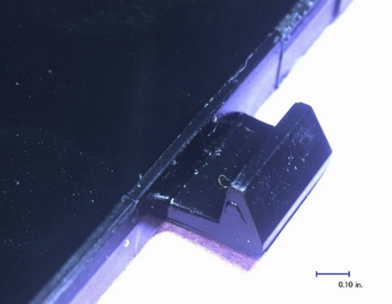
Figure 2: Lower Snap-fits.
The design of the faceplate consisted of a black polycarbonate plastic with a grill pattern and multiple assembly points. The part was mounted at the bottom by the use of snap-fits that mated against another component. Figure 2 shows a view of the snap-fit design. When assembled, there was a lot of play in the components. In fact, the snap -fits acted more like hooks, since the part could essentially be installed at an angle by aligning the hooks into the lower slots on the mating component, and then moving the faceplate up into place. I imagine that the aggressive design angles on the snap-fits required a loose fit. Otherwise, the snap-fits would not have been able to be removed after installation for accessing and replacing the carbon filter.
In order to prevent the faceplate from falling, the assembly used three screws that were inserted over the top of the microwave through a metal plate and into small tabs of about ¾” in width along the part. These tabs were completely broken into multiple pieces. In Figure 3, the top photo shows a schematic of what they should have looked like. The three screws consisted of small non-plastic specific thread forming wood screws that created interference and stress to the tabs. In addition, the sheet metal holding the tabs was designed as a groove that required some force to push the tabs in and hold them in place. Overall, there appeared to be a lot of stress on the tab area resulting from the interference of the screws, the tightening force, and the force of the metal squeezing the tabs in place. This was pretty obvious by the fact that I had to use pliers and a flat head screwdriver, with some force, to push out all the broken pieces of tabs from the slots, even after removing the screws.
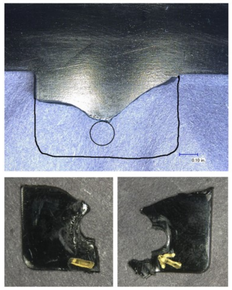
Figure 3: Upper tabs general design (top). Remaining broken tabs (bottom).
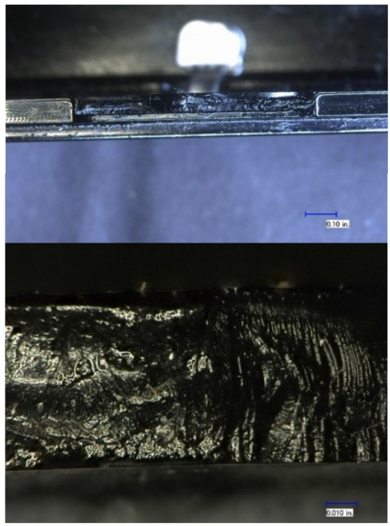
Figure 4: Fractures covered in oil.
A closer inspection of the pieces of broken tabs showed oily residue in the cracks and surrounding areas. This tab location is directly exposed to the flow of air from the hood and would likely carry cooking oils through the air. I was pretty convinced of what to expect when examining the fracture under a microscope, but it is always a good idea to confirm your hypothesis with real data. Examination of the fractures “as-is”, was prohibitive as they were covered in oil, Figure 4. After cleaning, it was evident that the fractures were not consistent with a failure caused by an impact or user abuse. The fractures showed slow-crack growth features and banding consistent with an environmental stress cracking (ESC) mode of failure, Figure 5. ESC is a phenomenon that allows a plastic material to crack when under load and while exposed to a chemical. If the plastic is not under stress, the part will not necessarily crack by the chemical agent. This was evident in all the other locations of the faceplate that were coated with cooking oil, but showed no cracks. The polycarbonate material had only fractured at the tabs that were experiencing high stress from assembly.
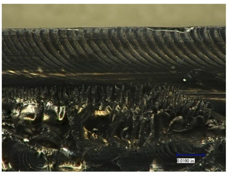
Figure 5: View of an ultrasonically-cleaned fracture.
Examining the fracture using a scanning electron microscope (SEM) highlighted the ESC features and allow to positively confirm the mechanism that was driving the cracking, Figure 6. Based on the SEM analysis it was clear that the cracking was driven by ESC. In addition, certain progressions of cracks showed features consistent with cyclic loading. It is likely that the vibrations of regular use, whether from opening/closing the microwave door, or from the hood fan contributed to crack propagation.
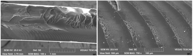
Figure 6: SEM views of the fracture.
Figure 7 includes an FTIR spectrum of the oil residue contained on the fractures. The spectrum shows a strong hydrocarbon and ester functionality similar to most fatty acid esters. Many cooking oils will have a similar spectrum to the one shown, as identified by the examples of coconut oil and palm oil. It is well-known and documented that polycarbonate can be sensitive to ESC for these types of chemical substances. Additionally, those effects can be accelerated with exposure to elevated temperatures. In this application where the part will likely be exposed to hot cooking oils, the damaging effects are of greater concern and the risk for failure will increase.
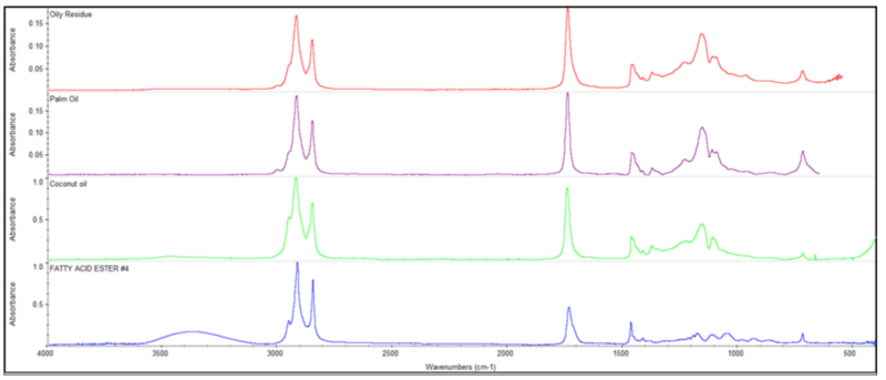
Figure 7: FTIR spectrum of oily residue with similar matches to various cooking oils.
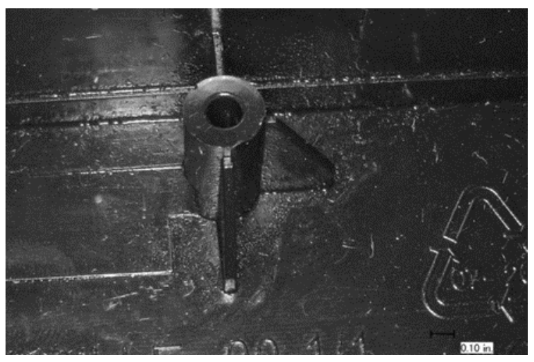
Figure 8: View of one of the bosses in the assembly.
Looking further into the design, it was interesting to note that the interior of the assembly included some bosses that did not appear to have any purpose of being there, Figure 8. The design appeared typical to what would be used to install an assembly by inserting a screw into the holes of the bosses. I wonder if this component was designed-in and someone realized that the idea of supporting the assembly by these bosses was probably not the best due to the high stress they would have encountered. Maybe, the bosses were also a poor design because they would be hard to access. In any case, it was a good thing that no screws were inserted into the bosses. Unfortunately, the same was not done for the top of the faceplate, and thread forming screws were placed against tabs that were constrained and under high stress. A better design would have focused on making sure that the part was completely free of elevated assembly stresses, in order to avoid the chances of a premature ESC failure.
In this article, we are not diving into alternative options of design or materials, but I have to say, that there are a number of changes that could have been implemented in order to avoid this failure.