Once a part is assembled and/or molded, the internal geometry, along with possible defects, may not be visible from an exterior examination. This can result in problems going undetected that may lead to poor performance and possible failures over time. Two essential techniques that are commonly used to fully analyze plastic parts/assemblies are computed tomography (CT) imaging and mechanical cross-sectioning. CT imaging is a non-destructive technique that creates a digital three-dimensional representation of the part/assembly. Whereas mechanical cross-sectioning is destructive; requiring the part to be cut and polished at a predetermined plane. Each technique has its own advantages and disadvantages. However, both of these techniques allow the engineer to analyze, understand, optimize and prevent/fix failures that otherwise may go undetected.
Computed tomography imaging works by detecting differences in density between components being scanned. This technique generates multiple (typically 100s to 1000s per part) two-dimensional x-ray images that are digitally stitched together to produce a three-dimensional representation of the component or assembly. This allows an individual to examine the interior and exterior features of the part/assembly that may not be possible with basic visual analysis.
Using computer aided software, a user can scroll through multiple planes, angles and rotations to produce a two-dimensional sectional image anywhere throughout the part/assembly, Figure 1. Furthermore, with CT imaging, measurements can be taken, voids/cracks/misalignments can be detected and levels of porosity within a part can be quantified.
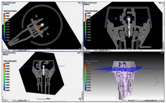
Figure 1: Two-dimensional views at multiple planes.
Mechanical cross-sectioning involves the physical cutting of a part/assembly at a predetermined location; followed by a multi-step polishing process for the cut surface, Figure 2. To help support/lock components, the assembly can be mounted in epoxy before or after the cutting process, prior to the polishing step. The cutting process is obviously destructive and will alter the current state and condition of the part/assembly. Typically, one or two cross-sections can be made of one part/assembly. Thus, the location of the interested plane is an extremely important step. Overall, the mechanical cross-section can often allow for a higher resolution inspection when compared to computed tomography imaging, which allows for better detection of cracks and defects.
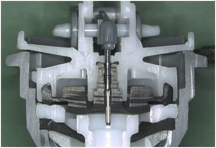
Figure 2: View of a cross-sectioned assembly.
CT imaging and mechanical cross-sectioning are different techniques that can be used separately or in conjunction with one another. The most substantial difference between the two techniques is CT imaging is non-destructive, while cross-sectioning is destructive. Therefore, if the part/assembly cannot be altered, CT imaging is the most viable option.
CT imaging comes with the disadvantage of producing grayscale images (the part color is lost). As stated, computed tomography imaging distinguishes between differences in density. There are great advantages to this technique when analyzing polymeric or rubber components/assemblies. However, substantial differences in density can create issues, e.g., metal inserts in a plastic part. This combination can create a “sun halo” effect around the metal part, blurring-out possible areas of interest within the image, Figure 3. The grayscale imagery does not allow for clear examination of mixing, weld joints and knit lines. Mechanical cross-sectioning may be the preferred method when analyzing these processing-induced anomalies.
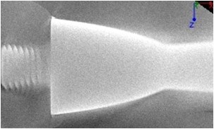
Figure 3: CT imaging showing a metal component next to a polymeric, “sun halo” effect.
When a fracture occurs in a part, the crack/puncture will create a void at the separation of the two surfaces, which will change the density in that area and make it visible, Figure 4. However, the separation of the two surfaces must be within the detection/resolution limit of the CT scanner being used. Therefore, depending on the part size and resolution of the CT imaging, the separation created by a hairline crack may or may not be visible. Overall, the resolution level will increase with decreasing the part size. Therefore, CT resolution is best when analyzing a small part or region of interest. However, big parts offer a high degree of complexity/effort when conducting a mechanical cross-section. Therefore, a CT image can offer an alternative method to develop a cross-section regardless of the reduction in resolution.
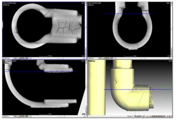
Figure 4: Imagery showing crack formation within a part.
The use of mechanical cross-sectioning allows for analysis of a single plane in the part. This works well if a crack, void or other anomaly crosses the sectioned plane. However, it is possible that anomalies are present away from the sectioned plane. This is where computed tomography imaging is most powerful. It provides limitless digital cross-sectioning and allows the analyst to peer into the part at any location, angle/rotation or magnification (within the tolerance of the instrument). Therefore, the CT images can determine the precise location/plane of interest. At this point, CT imaging can be coupled with mechanical cross-sectioning. CT imaging can be used to select the location of interest that may not be readily visible on the part/assembly. Proceeding the CT analysis step, a mechanical cross-section can be performed to inspect the location of interest.
Please check out our related articles here: Cross Sectioning as an Analysis Tool and CT Imaging of Plastic Parts – Non‐Destructive Analysis.
This article was originally published by Dayton S. Ramirez, Dr. Javier Cruz, and Dr. Paul J. Gramann.