This article was originally authored by Matt Dachel.
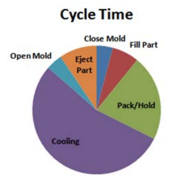
Figure 1 – Pie chart representing a
typical injection molding cycle.
A key benefit of injection molding is the ability to economically mass-produce dimensionally stable parts. The injection molding cycle can be split up into four main stages: filling, packing, cooling and ejection. In general, the cooling stage can comprise around 50-80% of the cycle time, Figure 1 (1).
In addition to having a significant influence on the cycle time, the cooling stage can also have a drastic influence on the part performance. The part surface appearance, chemical resistance and dimensional stability can all be influenced by the cooling parameters used during processing. The cooling time is most often dictated by the thickness of the part and feed system, as well as the mold temperatures. As shown in Figure 2, while both the part thickness and mold surface temperature can impact the cycle time, the part thickness typically will have a much larger influence on the cycle time than the mold temperature. Therefore, part designers should pay attention to their selection of the nominal wall section, when they want to optimize part cost without sacrificing part quality.
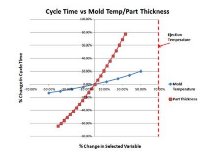
Figure 2 – This image highlights that part design has a much larger influence than mold temperature on the overall cooling performance and cycle time for a given part.
In some cases, if the cooling line layout is not optimized wide mold temperature variations and high mold temperatures can develop. This is particularly true with tall, slender cores, where it can be difficult to get cooling close to the part surface. As the mold temperature approaches the ejection temperature of the material, the influence of the mold temperature on the cycle time sharply increases, Figure 3.
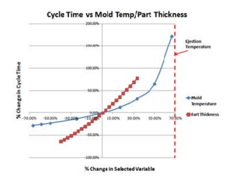
Figure 3 ‐ Graph displaying the percentage change in cycle time versus the percentage change in mold temperature and part thickness.
The hot surfaces of the part will also take longer to solidify and thus, shrink more than the colder regions of the part. This effect can result in the buildup of stresses in the part. These internal stresses can manifest as part warpage (Figure 4), but can also remain as residual stresses, if the part is rigid enough to resist the warpage (2).
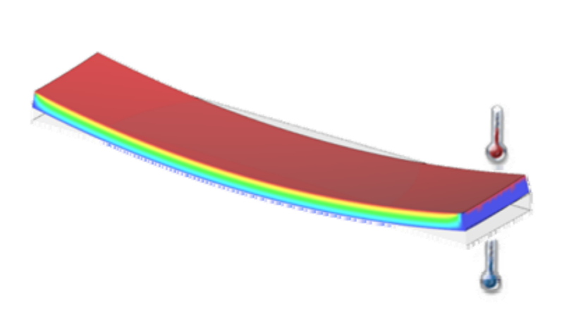
Figure 4 ‐ Temperature differences, from one side of the mold to the other, can lead to layers freezing and shrinking at different times and generating internal stresses.
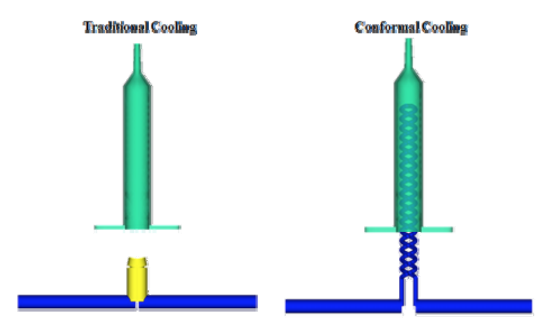
Figure 5 – Traditional cooling channel layout (left) and conformal cooling channel layout (right).
While it is well-known that cooling the part uniformly is important for the performance of the part, the design of the cooling system is often left toward the end of the mold design process. Therefore, the design freedom of the cooling system is often limited. Additionally, the cooling channels must avoid the already designed features of the mold, such as slides and ejector pins, and also must maintain the structural integrity of the mold. The cooling channels are typically drilled into the mold, which most often requires that the cooling channels are designed as straight lines. Combine these limitations with complex part designs and uniform cooling of the part may be difficult to achieve with traditional methods.
One solution to this problem is utilizing conformal cooling channels. Molds and mold inserts with conformal cooling channels are typically built utilizing additive manufacturing, such as direct metal laser sintering (DMLS), which builds the tool in thin layers from the bottom up. Building tools in this way allows the cooling channels to be created without drilling through the mold, and allow a much greater freedom when designing the cooling system, as shown in Figure 5. Conformal channels allow the cooling system to follow the profile of the part. The cross-sectional shape of the channel can also be modified to allow the conformal channel to fit into many tight areas, where traditional channels may not be able to reach. At this time, high conductivity materials, such as beryllium copper (BeCu), are not readily available for 3D printed tools.
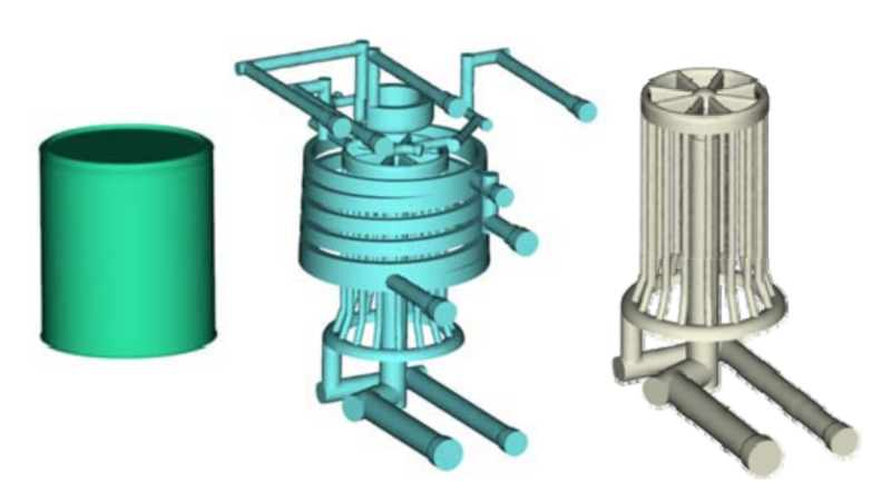
Figure 6 –A conventional cooling line layout, using traditional machining methods is shown for a quart container.
Injection molding simulation software, such as Moldflow, can be utilized in order to simulate the injection molding process and calculate the mold temperatures, as they fluctuate through the injection molding cycle. As an example, a toolmaker provided the mold layout for a quart-sized container. Figure 6 shows the cooling line layout from the container mold that was used to manufacture the container. The mold was designed and manufactured using traditional machining methods. In order to achieve this cooling channel configuration, several inserts needed to be machined and assembled together. This cooling configuration was modeled with both steel and a high-conductivity (Moldmax) material for the Moldflow analysis. Additionally, a steel core insert with conformal cooling channels (Figure 7), was designed in order to compare cooling to the traditional inserts. The channel near the inner corner of the quart can was designed with a triangular cross-section in order to reach closer to the inner corner of the tool, where the highest heat load was expected.
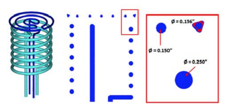
Figure 7 – An additive conformal cooling channel design, shown as blue were integrated into the core insert (left). The cross‐section of the cooling channels are shown in the two images to the right (middle and right).
The predicted mold surface temperatures are shown for each of the mold inserts in Figures 8-10. The high conductivity insert and conformal cooling insert (Figures 9 and 10), were predicted to run approximately 17 °F cooler at the hot inner corner of the mold than the traditional steel insert (Figure 8). Both the conformal cooling insert and the high-conductivity insert showed a similar improvement of the mold temperature distribution, when compared to the traditional cooling line layout and steel insert (Figure 8). In this case, the part design allowed enough flexibility to design a core cap insert that achieved relatively uniform mold temperatures using traditional machining methods. However, the traditional channel design needed to utilize a high-conductivity material in order to uniformly cool the inner corner of the mold. The conformal cooling insert displayed uniform mold temperatures without the need of high conductivity materials.
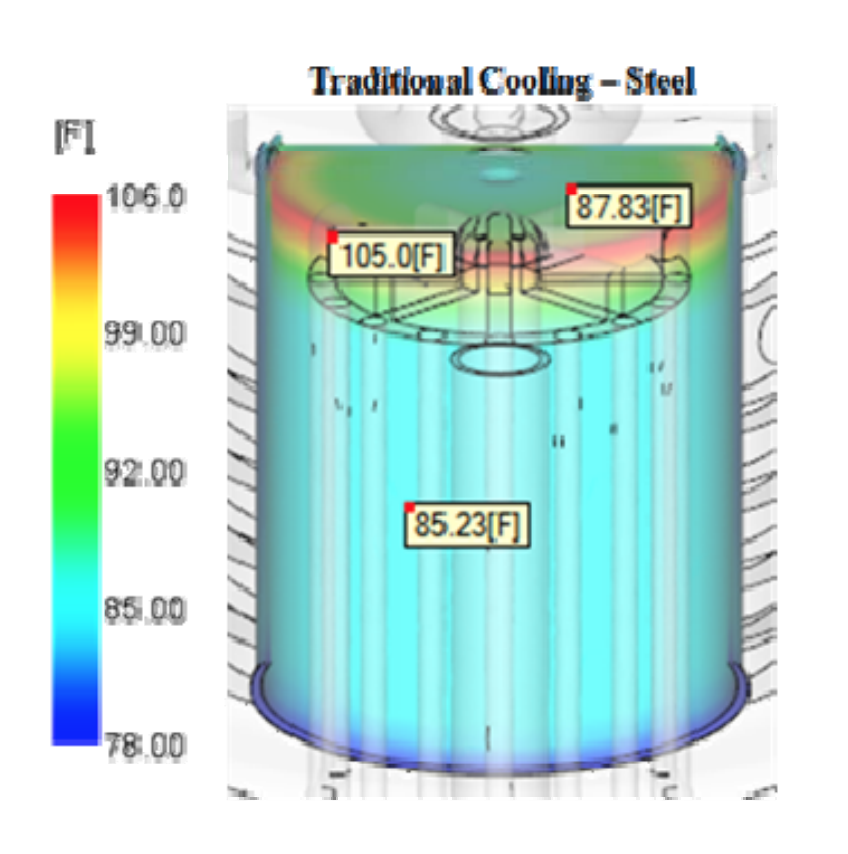
Figure 8 –Mold surface temperature of the steel mold insert with traditional cooling channels.
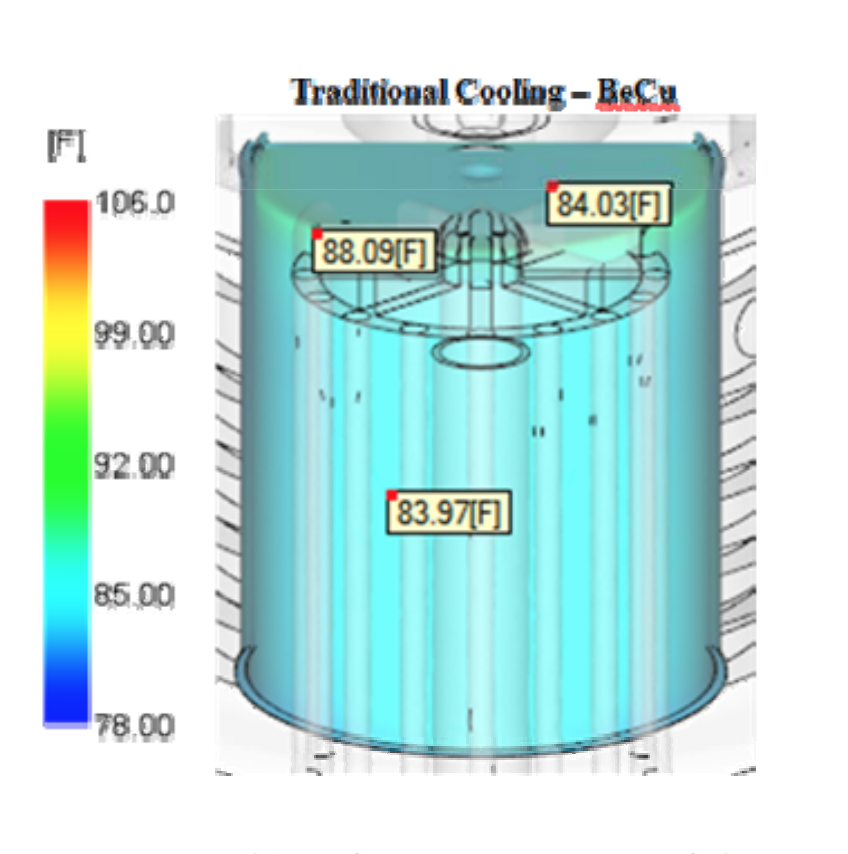
Figure 9 ‐ Mold surface temperature of the high‐conductivity (BeCu) mold insert with traditional cooling channels.
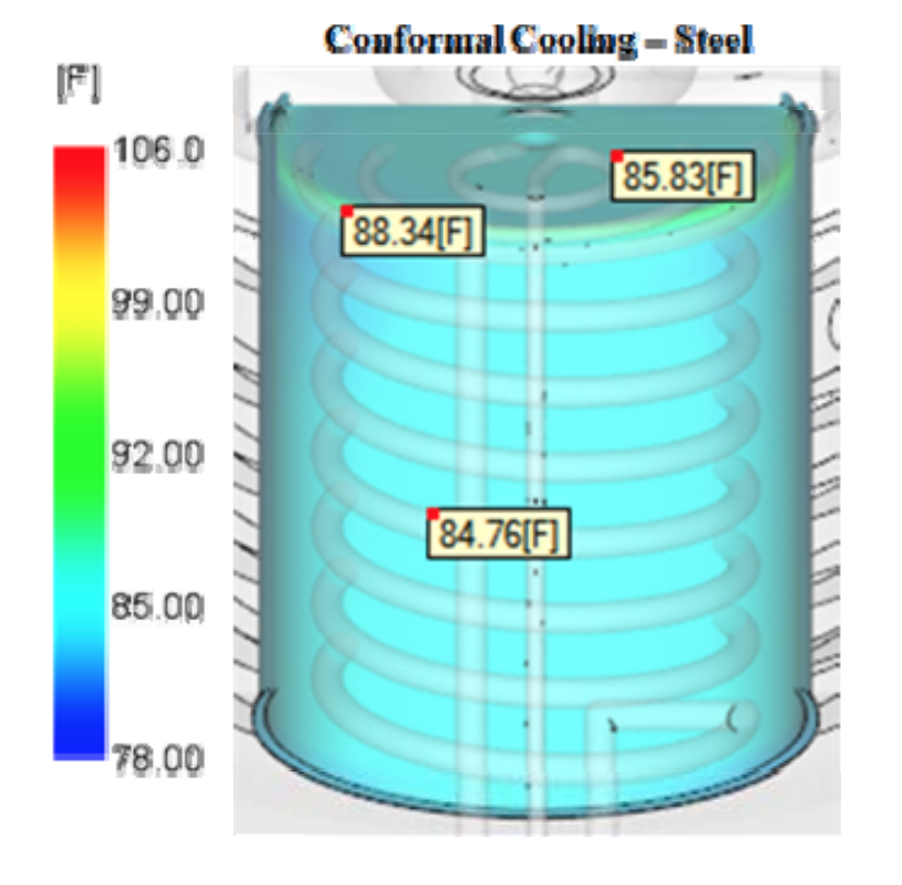
Figure 10 ‐ Mold surface temperature of the steel mold insert with conformal cooling
channels.
Summary
This article displays one example in which conformal cooling channels were investigated for injection molding to promote uniform cooling of the mold. In general, conformal cooling channels can improve the mold temperature distribution and may reduce the cycle time, when compared directly with traditional cooling channel designs. Conformal cooling lines typically show the most benefit when the limitations of traditional cooling lines restrict the ability to get cooling lines close to the part surface. Examples of this type of scenario are parts with deep pockets and confined spaces that may not allow for cooling channels to be drilled into these locations. Conformal cooling channels can increase mold design flexibility as well, and can allow cooling channels to cover more of the part than traditional cooling lines would allow. However, for parts that allow plenty of space for traditional cooling lines to uniformly cover the part, such as with a flat plate, conformal cooling lines may not yield a significant benefit over traditional mold construction needs. Injection molding simulation can be very useful when deciding if conformal cooling channels should be used for a given mold. These tools can help predict the hot spots in the tool, and quickly evaluate the effects of different cooling system designs.
(1) Subramanian, M. N. (2011) Plastics Processing, in Basics of Troubleshooting in Plastics Processing: An Introductory Practical Guide, John Wiley & Sons, Inc., Hoboken, NJ, USA.
(2) Fischer, Jerry. (2013). Handbook of Molded Part Shrinkage and Warpage (2nd Edition). Elsevier.