Industry trends have pushed toward the miniaturization of devices and assemblies. One important consideration with miniaturized components is core deflection, as this can affect the quality of the final product. This often means that the enclosures and connectors we use now are integrating deep, narrow cavities, which reduce the overall profile of the device. Additionally, the components still need to maintain good feature definition internally because they are housing valuable electronics or forming a pathway for fluids to flow in the assemblies.
Thin cores need to be integrated into our mold design to form these cavities, and these thinner cores can be prone to deflection or poor feature replication caused by poor cooling. While there are benefits to reducing the size of the enclosure for the consumer, these designs can introduce unique challenges in injection molding. This article highlights some important manufacturing considerations to account for to ensure these products perform as desired. It also demonstrates how injection molding simulation can help identify the risk for potential issues prior to first shots.
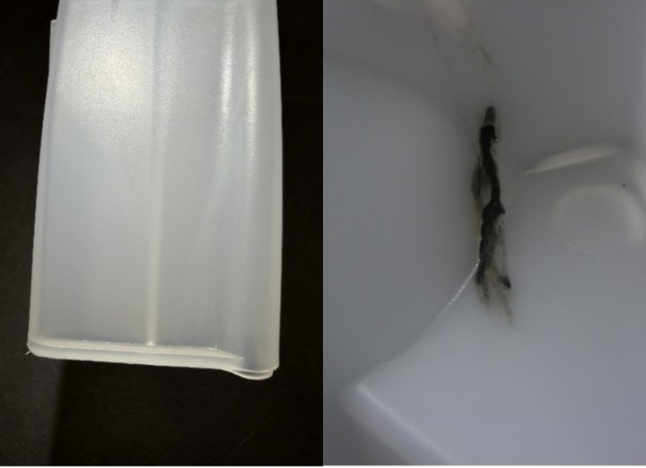
Core deflection can result in defects like unexpected weld lines (left) and air traps and burning (right).
Gate Location and Core Deflection
When dealing with parts that have long, slender cores, gate location is critical to ensure a robust molding process. Standard guidelines for gate location in injection molding are numerous, but there are additional consideration for parts that have deep cores that could deflect during molding. If the gating is not optimized, the flow around the core can be biased to one side and lead to core deflection that causes air trapping, short shots, flash generation and non-uniform wall thicknesses in the part (picture at the left).
The key factor to consider when gating a part with a long, slender core, is how to achieve a balanced, uniform filling pattern along the entire height of the core. By having the material flow up the core uniformly, the pressure should remain relatively consistent on all sides, helping keep the core in place. With the high injection pressures commonly experienced during molding, even a slight imbalance from side to side can lead to significant core deflection that will adversely affect part quality. This is particularly important for cores that have a height-to-thickness ratio of 3:1, or greater, and are unsupported at one end.
To help promote balanced and uniform filling pattern along the core, the preferred gate locations would be at the top or base of the core. These locations allow material to get around the core early in the mold-filling stage, helping keep the core centered later on in the molding cycle. Alternatively, the molder could elect to use multiple, symmetrically placed gates, or a diaphragm gate, but these options often lead to higher-cost parts with the potential for increased scrap and the introduction of weld lines that reduce part strength. Therefore, the cost of making the wrong decision can be detrimental to the product’s success and development timeline.
Injection molding simulation packages, like Autodesk Moldflow, can simulate different gate locations early in the process of designing a product or mold to assess how gate placement could influence core deflection. Performing core-shift analyses helps avoid any costly mold rework often only identified during initial sampling of the mold. Typically simulation is used to represent the plastic molded part and feed system only. However, simulation packages can simulate the entire mold and molding process, including any standing cores, to see how the steel will move during the mold filling and packing stages (Figure 1).
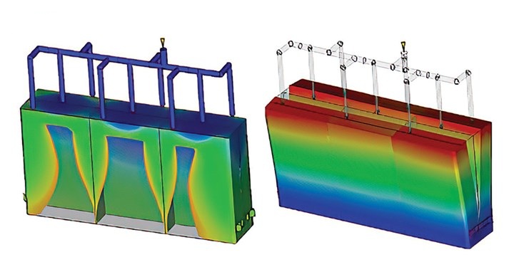
Figure 1. If gate location results in non-uniform flow down the cores, it can lead to deflection of the cores and non-fill areas.
When the cores are included in the study, the simulation will perform a coupled fluid-structural-interaction (FSI) simulation to determine how the standing steel will deflect due to any non-uniform flow around it. This calculation is a dynamic one, with the calculation performed incrementally at unique time-steps as the flow progresses into the cavity. During each of the time-step calculations, any core shifting will also change the resultant part thickness that is trying to be filled in the cavity. If the part’s wall thickness is reduced enough, the material may hesitate and result in unintended air traps or short shots in the part.
Core Shutoffs and Core Material Selection
Core-deflection simulations can also account for having multiple telescoping or interlocking cores that touch when the mold closes. Depending on the design of the core shutoff, the different cores could still shift during the mold-filling stage due to designed-in clearances and non-uniform flow around the cores (Figure 2).
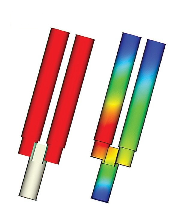
Figure 2. Injection molding simulation can anticipate how multiple interlocking cores (left) will deflect during the molding cycle (right).
Allowing the cores to move relative to one another could result in generating unintended flash, as well as high-contact stresses that could result in premature core failure. By simulating the different potential interactions between the cores, the molder and mold designer can better understand the benefits for pursuing one shutoff strategy over another.
While the movement of the cores during a single mold cycle may or may not cause part-quality issues, it can influence the overall durability of the mold component. The expectation of injection molding is that we will be able to produce thousands to millions of parts. Therefore, even if the core deflection is not excessive, the stress generated in the core can eventually result in fatigue failure of the components. Simulating the cores reveals information about the stress magnitude and distribution that can help identify potential stress hot spots, which might lead to fatigue failure of a mold component (Figure 3).
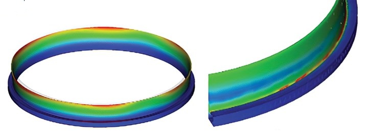
Figure 3. In addition to getting an idea of how a core will deflect under molding pressures (left), the stress distribution through the core (right) can also be quantified to help better identify proper core material selection and design.
Identifying these stress hot spots allows for the molder and designer to make better decisions on how to manufacture and integrate the core into the mold design, including what material should be selected to endure high stresses.
Cooling of Cores and Cycle Time
A final area to consider during design when integrating long, slender cores into a mold, is how the core will be cooled during the molding cycle. Plastics require a tremendous amount of heat energy to get into the molten, flowable state. Once injected into the mold, that heat energy must be extracted from the molten plastic so it can resolidify and be ejected out of the mold. With long slender cores, it can be difficult to get cooling lines integrated deep enough into the cores to extract the heat quickly enough from the plastic material and core. This inability to extract the heat can lead to mold hot spots that require longer cycle times. Hot spots can also impact surface replication or lead to material sticking since plastic cannot cool sufficiently within the cycle to withstand any ejection forces (Figure 4).
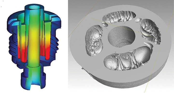
Figure 4. Simulation shows the hot spots of the core (areas shown as red), leading to poor surface replication at the tips of the cores, as seen in a CT scan of the part (right).
Injection molding simulation can again help identify these hot-spot risks in the slender cores by simulating the proposed core design and cooling line layout to determine whether or not the proposed mold design can mitigate these issues and maintain a uniform mold surface temperature within the quoted cycle time.
Proactive measures can be made to pivot the mold design strategy to achieve the desired cycle time by either changing the mold core material or the cooling line strategy, if the simulation suggests there may be hot spots. Regardless of the solution, it will likely mean the mold will be more expensive than initially quoted or anticipated. Therefore, running the simulation can help gain alignment among various stakeholders on the right strategy given any budgetary and/or design constraints.
Manufacturing parts that require long, slender cores to be integrated into the mold design offers a unique set of challenges. While each part is distinct and has its own constraints, taking a holistic look at the gating strategy and the mechanical and thermal optimization of the slender cores will help avoid many issues that could adversely affect part quality or mold yield. By using injection molding simulation up front, many of these issues can be addressed proactively before first shots are made, saving both time and money for all stakeholders.
This article was originally published in the January 2026 edition of Plastics Technology.