It is well-known that fiber reinforced plastics, or FRP composites, offer great potential to designers and OEM’s in bridging the gap between polymers and metals. Adding a reinforcing filler, like glass fibers or carbon fibers, can improve the stiffness, strength, creep resistance of a base material, and can help extend the upper limit of the short-term temperature exposure of a given base material. The addition of fibers can also help reduce the shrinkage of a resin, which makes it attractive for tight tolerance parts. It is also a well-publicized, but less well-known fact that the addition of glass-fibers only offer the potential for better properties in a plastic part. As described in Optimizing Strength and Stiffness of a Plastic Part, the benefits for the addition of fibers are dependent on aligning the fibers in the same direction as the loading direction for a given part or assembly. What is least well understood by most designers and OEM’s is what dictates the fiber orientation in the end component, and how much control we actually have on helping develop that orientation. This article will highlight what controls the fiber orientation in parts manufactured using the injection molding process, and what decisions during the design process can help us get the most from these materials to optimize part performance and minimize part warpage.
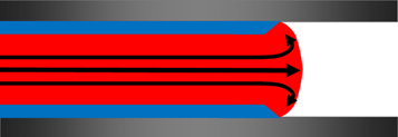
Figure 1: Schematic showing fountain flow in injection mold.
What Dictates Fiber Orientation in an Injection-Molded Part?
During the injection molding process, the plastic material is heated up to a temperature that allows the polymer resin to flow when pressure is applied. These temperatures required to get the polymer to flow are much lower than the melting point for the glass or carbon fibers. Therefore, we are left with a molten material, the matrix, that has solid fibers that are suspended in the fluid. When the molten material is injected into the mold, forces develop in the fluid that elongate the molecules and orient the fibers in the direction of those applied forces. Because of the dynamics of polymer flow in the mold, this leads to a type of flow often referred to as fountain flow, where the material tends to flow from the center of the wall section out toward the mold wall, Figure 1. Therefore, we have two different deformational forces through the cross-section of the flow path. Along the centerline of the flow path, the elongational forces orient the fibers perpendicular to the flow path, while the shear forces at the mold wall will tend to orient the fibers in the direction of flow, Figure 2. This leads to a skin-core structure for the end molded part that is dictated by how the material flows into the cavity. The exact variation through the cross-section can be influenced by many molding parameters such as injection speed, and melt and mold temperature.
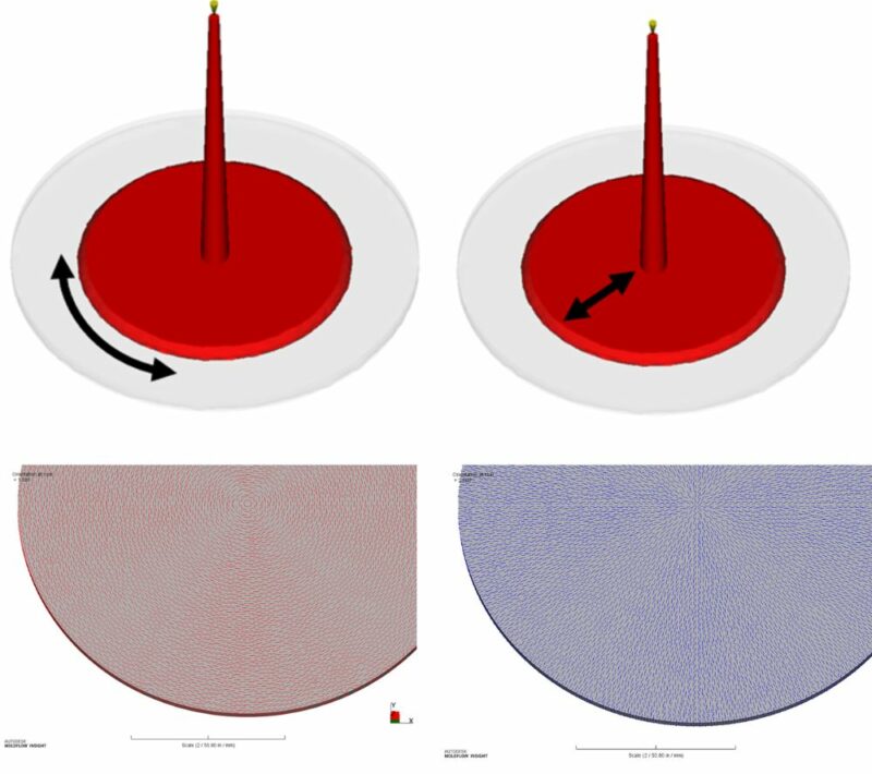
Figure 2: Deformational forces during flow lead to variable fiber orientation through the cross-section of a part often referred to as skin-core structure. Elongational forces at the center of the wall (core) orient the fibers perpendicular to the flow direction, images on left. Shear forces At the skin orient the fibers parallel to the flow direction, images on right.
What Dictates Polymer Flow In Cavity?
While the exact processing parameters used can influence the end fiber orientation in a given part, the most important factor that influences the fiber orientation for a given part is the gate location. The gate is the location on an injection-molded part is the location where the plastic starts to flow and form the end part that needs to be made. Designers often dictate locations where the gate cannot be placed, but will leave the exact gate location decision to the molder or toolmaker. This single decision will have a critical influence on the expected fiber orientation in a part. General guidelines for selecting a gate location to aid in optimizing fiber orientation include:
- Positioning the gate in the thickest wall section of the part.
- Minimizing the changes in flow direction from the gate to the end of fill. This is often referred to as achieving a unidirectional filling pattern.
- Allowing the material to flow in the direction of loading to help align fibers or molecules.
- Positioning weld lines in non-critical locations.
- Allowing the molten plastic to hit a wall and establish a uniform flow front.
- Positioning the gate away from any impact locations or high stress locations.
Figure 3 highlights that for a given part geometry, even a slight change in the gate location relative to the orientation of the part can have a drastic change on the resultant fiber orientation in the end molded part. This will influence the end properties of the molded product and could make the difference between a part that functions properly and one that fails. If the fibers do not align with the loading direction, cracking or excessive distortion could occur and affect the end performance of the part, Figure 4.
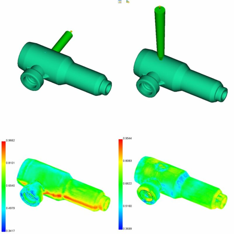
Figure 3: The selection of where to place the gate will influence the weld line position and end fiber orientation in a part. Images on the top show two different gate locations/configurations and how the expected fiber orientation changes in a part, bottom images.
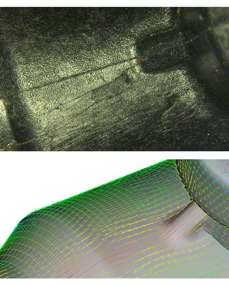
Figure 4 – If fiber orientation is not aligned with loading direction, premature cracking can occur. The top image highlights axial cracking. Bottom image highlights fibers are not reinforcing in crack orientation.
How to Proactively Optimize Gate Location and Expected Fiber Orientation
Clearly, the decision of a gate location is an important one for any injection-molded part. But particularly for fiber-reinforced plastic parts. While there are many factors that will influence the end performance of a part, it is not necessary to wait until the mold is constructed and first parts are produced to see if the part will fail or succeed. Waiting until the mold is constructed can lead to costly molding trails and non-ideal solutions to the end problem that could lead to reliability issues in the field. To help address these concerns, designer and molders can utilize structural simulation, FEA, using the conservative cross-flow properties of the resin to optimize their product design. Additionally, integrating tools like Autodesk Moldflow can help the team proactively address the design issues to see how those aspects would affect manufacturability and dimensional stability of a part. Moldflow can also help the designers optimize the gate location to position weld lines and develop the desired fiber orientation prior to even having a full tool design. Performing these up front simulations will help provide a clearer direction for suppliers and will set the product up for success where the tooling tuning cycle is reduced.
Give us a call, if you are struggling with a plastic part performance, or would like to hear more about how to consider these manufacturing aspects of your plastic part design proactively. You can reach us here.
Furthermore, if you’re interested in training to better utilize injection molding simulation for optimizing fiber orientation in your fiber-reinforced part manufacturing with Autodesk Moldflow, explore our course MLD-517.
Authored by Erik Foltz and Tom Hansen.