Cracking – the partial fracture of a solid material – occurs as a result of the exertion of stresses, both external and internal, on a component. Cracking is simply a stress relief mechanism in which the material is attempting to reach a lower energy state. Contrary to popular belief, mechanical stresses do not break the covalent polymer backbone bonds. Instead, the stresses overcome the intermolecular forces, such as Van der Waals forces and hydrogen bonding that keep the polymeric molecular structure intact. Plastics fail through a disentanglement mechanism in which polymer chains slide past each other. Given sufficient stress, the disentanglement leads to cracking, and catastrophic failure occurs if the cracking extends sufficiently through the material. Cracking can be
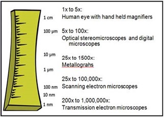
Figure 1 – Various techniques can be used to study a fracture surface during a fractography.
generally categorized into ductile or brittle fracture. Ductile cracking occurs after significant deformation and yielding. Ductile fracture is a bulk molecular response through yielding (macro molecular rearrangement) followed by disentanglement. Brittle fracture is a localized molecular response where disentanglement is favored over yielding.
The goal of a failure analysis is to ascertain the mechanism and cause of the failure; more simply, to determine how and why the part failed. Much of the information regarding the failure mechanism can be gleaned by interpreting the features found on the fracture surface. The examination and interpretation of the fracture surface is known as fractography. Fractography begins with a thorough macroscopic inspection of all of the failed parts. This is typically followed by examination at increasing magnifications using a stereomicroscope, a digital microscope, and when necessary a scanning electron microscope (SEM). There are numerous tools that can be used to examine and evaluate the fracture surface, each offering different strengths and providing unique information (Figure 1).
Cracking produces two mating fracture surfaces. The features on the fracture surface are created based upon a number of parameters:
- Type of material and formulation constituents
- Type of applied forces (tensile, compression, shear)
- Magnitude of forces
- Frequency of forces (continuous, intermittent, rapidly applied)
- Environmental effects (temperature, presence of chemical)
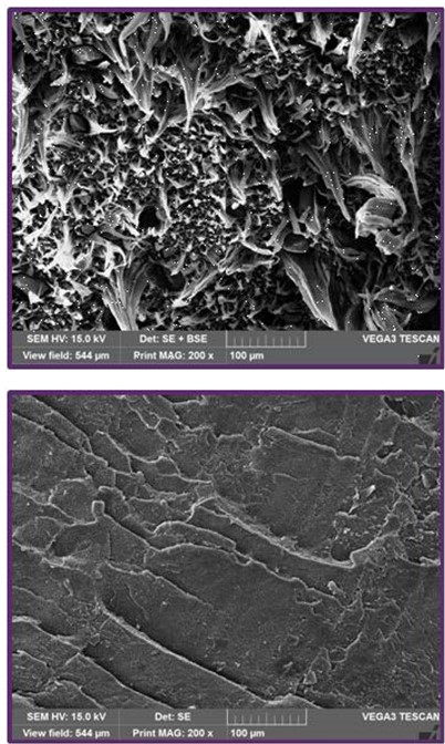
Figure 2: SEM images showing ductile (upper) and brittle (lower) fracture surfaces.
The key to interpreting the fracture surface during the fractography is to be able to recognize and interpret the features left from crack generation. The first generality to be made regarding the fracture surface is the nature of the cracking, ductile or brittle (Figure 2). As indicated previously, ductile failure takes place substantial deformation associated with yielding. Macroscopically, ductile failure is often characterized by stress whitening and stretching.
Microscopically, ductile fracture surfaces generally exhibit the formation of stretched fibrils. In contrast, brittle fracture takes place without yielding, and is characterized by minimal deformation or elongation. On a macro level, the mating fracture surfaces of a brittle fracture will exhibit little separation with little distortion within the surrounding material. Microscopically the fracture surface is generally characterized by a smooth morphology or the presence of sharp angular features.
A key piece of information found on the fracture surface is the crack origin. The fracture origin is the location of crack initiation and usually corresponds to the area of maximum stress and/or the location with minimal strength (Figure 3). A fracture may have a single origin or multiple origins depending on the type of stress, the environmental conditions, and the part configuration. The fracture origin holds important information regarding the magnitude and orientation of the stress, as well as the physical environment at the time of the failure.
The morphology of the fracture surface provides information regarding the speed of the crack. Cracks can propagate at a wide range of speeds, from 1 mm/year to 1000 m/sec.1 Most often a smooth fracture surface morphology is associated with slow crack growth. In contrast, sharp distinct features most often signify rapid crack extension. In particular, crack bifurcation, the separation of a crack into multiple branches, occurs as the crack releases a high level of energy.
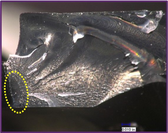
Figure 3 – Photomicrograph showing the origin are on a brittle fracture surface.
Beyond the origin and the overriding morphology of the fracture surface, there are many features that the fractography can provide to the failure investigator regarding how and why the part failed. These include:
Rib Markings: Also known as arrest markings, rib markings can be evident as faint indications or striations on the fracture surface (Figure 4). They are commonly formed when the moving crack front arrests. They can also be produced by dramatic transformations in crack propagation speed or changes in the environmental conditions.
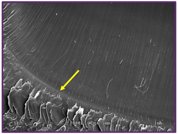
Figure 4 – Scanning electron micrograph showing a rib marking.
Crack Bifurcation: Crack bifurcation is the splitting of a single propagating cracking into multiple cracks (Figure 5). This is usually associated with conditions of relatively high energy input under which the crack is attempting to dissipate the energy as rapidly as possible. Crack bifurcation is generally linked to crack extension at higher speed.
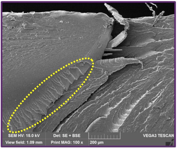
Figure 5 – Scanning electron micrograph showing crack bifurcation. River markings are also present (yellow dotted line).
Secondary Cracking or Mud Cracking: Secondary cracks are cracks present on the fracture surface that are formed perpendicular to the primary fracture. They are commonly formed through molecular degradation of the polymeric material.
River Markings: Associated with relatively higher crack propagation speeds, river markings are formed as the material dissipates the increasing energy of the stress (Figure 5). They are a sign of a significant increase in the crack extension rate or a change in the stress state on the part.
Crack Unions: The ridges formed by the unification of two separate cracks, crack unions, are usually oriented parallel to the crack propagation direction (Figure 6). The ridges often appear as steps and may exhibit more ductility in the form of stretching than the surrounding fracture surface.
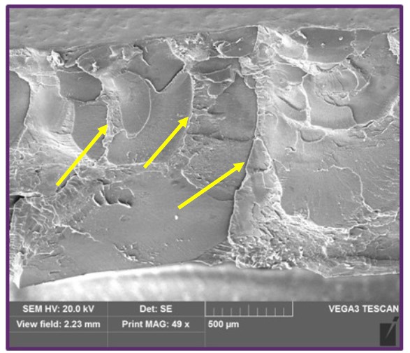
Figure 6 – Scanning electron micrograph showing multiple crack unions on the fracture surface.
Craze Remnants: Crazes are interpenetrating micro-voids with small fibrils bridging the two sides of the micro-voids. Crazing takes place under conditions of constant tension and are load-bearing. If the applied tensile load is sufficient, the bridging fibrils elongate and break, causing the micro-voids to grow and coalesce (Figure 7). Through coalescence of the micro-voids, cracks begin to form.
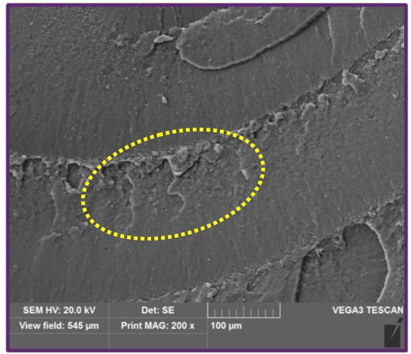
Figure 7 – Scanning electron micrograph showing remnants of an opened craze.
The challenging aspect of plastic fractography is that some features will have divergent meanings in different materials and under disparate stress conditions. As such, it is important to understand and take into consideration the type of plastic being examined. A thorough understanding of the material properties and experience with the tell-tale features are essential for the proper interpretation of the fracture surface.