In the field of polymer engineering, cracking is fundamentally viewed as a response to stress. A key area of interest is the fractography of polyacetal, where engineers analyze fracture surfaces of polyacetal materials. When a component’s internal or external loads exceed the material’s strength over a specific timeframe, the part undergoes stress-induced cracking. To accurately diagnose these failures, engineers utilize fractography, a forensic technique that examines fracture surfaces to determine the mode, magnitude, and direction of the failure-inducing stresses.
A recent failure analysis of a polyacetal (POM) copolymer component—utilized in a mechanical meter—demonstrates how the fractography of polyacetal can pinpoint the exact cause of a service failure. The component in question featured a cylindrical post extending from a main body, which had suffered a catastrophic crack at its base.
Fractography of Polyacetal – Macro-Examination and Stress Orientation
The initial phase of the investigation focused on the macro-orientation of the failure. The fractography of polyacetal revealed that the cracking was present as a transverse fracture, occurring perpendicular to the long axis of the post.
In cylindrical geometries, the direction of the crack provides immediate insight into the loading conditions:
- Longitudinal Cracks: These typically indicate hoop stress, often caused by internal pressure or interference fits.
- Transverse Cracks: These are characteristic of axial loading, which is frequently associated with tensile forces or bending moments.
The transverse nature of this specific failure, as confirmed by the fractography of polyacetal, indicated that the post was subjected to bending stresses that exceeded the material’s structural limits.
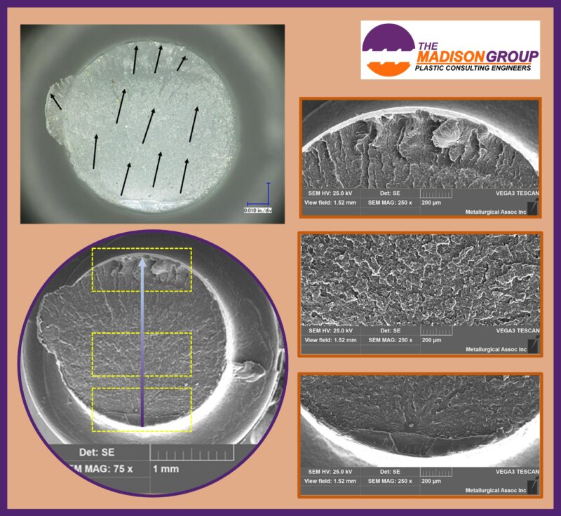
Fractography of Polyacetal – Microscopic Analysis: The Three Morphological Zones
Through microscopic and Scanning Electron Microscopy (SEM) inspections, the fractography of polyacetal identified three distinct zones on the fracture surface, each representing a different stage of the crack’s life cycle.
Zone 1: The Crack Origin
The fractography of polyacetal at the initiation site showed that the crack began along a small section of the post’s perimeter. The origin was located at a sharp design corner, which acted as a stress concentration point.
- Brittle Initiation: The surface texture at the origin was relatively smooth and lacked evidence of micro-ductility. These features are classic indicators of brittle fracture in the fractography of polyacetal.
- Crack Coalescence: Multiple initiation sites were apparent, separated by “ridge-like” features known as crack unions. These unions showed signs of localized stretching where individual crack fronts merged, a common observation in the fractography of polyacetal when multiple high-stress points exist.
Zone 2: Mid-Fracture and Micro-Ductility
As the crack moved away from the origin, the morphology changed significantly. The surface of polyacetal in this mid-fracture zone revealed an overlapping morphology. This texture is indicative of micro-ductility within the polyacetal copolymer, signifying that the material was attempting to plastically deform as the crack propagated at a more moderate velocity.
Zone 3: Final Fracture
The final area of the fracture surface represented the point of total structural instability. The fracture surface of polyacetal in this region showed features characteristic of rapid crack extension.
- Deformation: High levels of stretching and macro-deformation were observed.
- Mechanism: This zone confirms that once the crack reached a critical size, the remaining material underwent a rapid “snap” or final overload, completing the stress-induced cracking process.
Conclusion and Implications
The results of the fractography of polyacetal concluded that the cylindrical post failed via a mechanical overload mechanism. This failure was specifically driven by bending stresses that exceeded the short-term strength of the polyacetal copolymer. The location of the crack initiation correlated exactly with the area of highest stress calculated for a bending load.
By utilizing the fractography of polyacetal, it was determined that the failure was not due to chemical degradation or material flaws, but rather a design-load imbalance. To prevent future instances of stress-induced cracking, recommendations often include increasing the radius of fillets at the base of cylindrical features to reduce stress concentrations and ensure the applied loads remain below the material’s yield strength.
For more information on stress-induced cracking, check out this post, Cracking is a Stress Relief Mechanism.