Examining the injection molding process reveals that the majority of the cycle time is dedicated to cooling the part. Often accounting for two-thirds of the overall cycle time, the cooling stage of the process can have a significant influence on part quality. Additionally, it is the most beneficial stage to optimize and improve to reduce the cycle time. Yet, often the cooling layout is one of the last aspects of the mold design to be addressed. Cooling must be designed around mold functionality (slides, lifters, ejection system) and must not compromise the structural integrity of the mold. Simulating the cooling stage can help the designer understand what is happening inside the mold and determine how and if the mold design can be improved.
 An injection mold is essentially a heat exchanger. The molten plastic introduces heat into the mold, and the coolant extracts the heat out of the mold. The rate at which this heat can be extracted out of the plastic part is dependent several on factors – the plastic resin used, part geometry, mold material, cooling line placement and coolant conditions. These different factors need to be considered collectively in order to understand how to best cool the part and reach an acceptable cycle time.
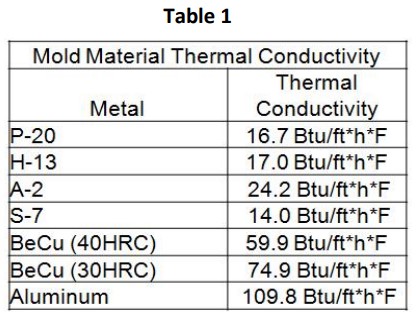
The goal when designing a cooling layout is to cool the part as uniformly as possible. Most mold designers try to achieve this by concentrating cooling circuits in high-heat load areas, and reducing the number of circuits in low-heat load areas. Mold designers will also incorporate high conductivity inserts in areas where they may feel they cannot get adequate cooling. Table 1 shows that alloys and metals such as Beryllium Copper or Aluminum have a much higher thermal conductivity than traditional tool steels. Using these higher conductivity steels can help maintain a lower mold temperature without requiring concentrated cooling lines. However, drilling cooling lines and incorporating high conductivity inserts costs money. A balance between part performance, optimal cooling, and cost must be obtained. Simulating the cooling stage and entire injection molding process can allow the mold designer to see how a design will perform and how it will influence the dimensional stability of the part.
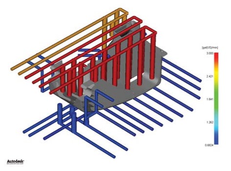
Figure 1: Simulation can help determine the required flow rate to achieve turbulent flow through the cooling circuits
How Can Simulation Help?
Once the initial mold design and cooling layout have been established, it is important to maximize the heat transfer between the part and the mold. With all other parameters fixed, the most important factor in determining how much heat can be extracted by the coolant is the flow rate through the cooling circuits, Figure 1. In order to maximize this heat transfer, the flow rate must be turbulent. Engineers use a dimensionless number called Reynolds number (Re), Eq 1, to help them determine when the flow has transitioned from the laminar regime to the turbulent regime. The Reynolds number is directly proportional to the flow rate, and density of the coolant, and is inversely proportional to the viscosity of the coolant. If the coolant used and the diameter of the cooling channel, D, are fixed, the only way to increase the Reynolds number and ensure turbulent flow is to increase the flow rate.
![]()
So what is restricting a molder from simply pushing as much coolant through a mold as possible? The answer is pressure. As the flow rate increases for a cooling circuit, the pressure required to maintain that flow rate also increases, and this requires greater pumping power. Once the flow has become turbulent, increasing the flow rate further provides diminishing returns in heat extraction while increasing the pumping power substantially. This extra energy consumption can reduce profit margins, while providing minimal benefit. Therefore, flow rate and pressure need to be considered together to help determine the optimal coolant conditions.
Even with an optimized cooling layout and mold construction, the geometry and material of the part may not allow for the desired cycle time to be achieved. From basic injection molding theory we know that the cycle time is directly proportional to the square of the part thickness, and is inversely proportional to the thermal diffusivity of the resin, Eq 2.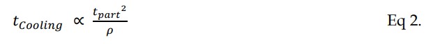
This means that if the wall thickness of the part is doubled, the expected cycle time would be quadrupled. This also means that the polymer chosen can influence the cycle time. While cycle time is not a high priority when deciding what material is best for the application, there are often several resins that meet the performance requirements. Additives such as talc, glass fibers, or carbon fiber can influence thermal properties of the base resin and allow the resin to cool faster. Awareness of the thermal behavior of the different resins could mean the difference between meeting the quoted cycle time or not.
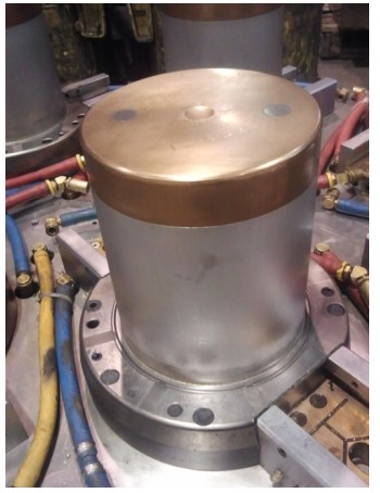
Figure 2: Core side of container mold showing Moldmax insert.
Case Study
A toolmaker was awarded a job to build a new mold for a plastic container. Part of the project scope was to modify the cooling layout to reduce the cycle time. The toolmaker decided to use simulation to help determine how to achieve this goal. The core side of the mold was designed to incorporate a Moldmax (Beryllium Copper) core cap, Figure 2, which would have two circuits cooling the cap. It was anticipated that using the higher conductivity insert would help remove the heat from the top of the core and cool this area most efficiently. A simulation was run with the proposed design, and revealed that the mold temperature was not reduced significantly enough to reduce the cycle time, Figure 3. Therefore, additional simulations were performed that used a cascading cooling circuit design to cool the core cap. Also, the plastic resin that was injected was changed. The new design increased the surface area of the cooling lines and helped maintain a cooler mold temperature which allowed the cycle time to be reduced. The change of resin further reduced the cycle time to allow the desired cycle time to be achieved. Through the use of simulation, time and money were saved by showing that the resin was limiting the cycle time and that the cooling layout had to be modified from its original design.
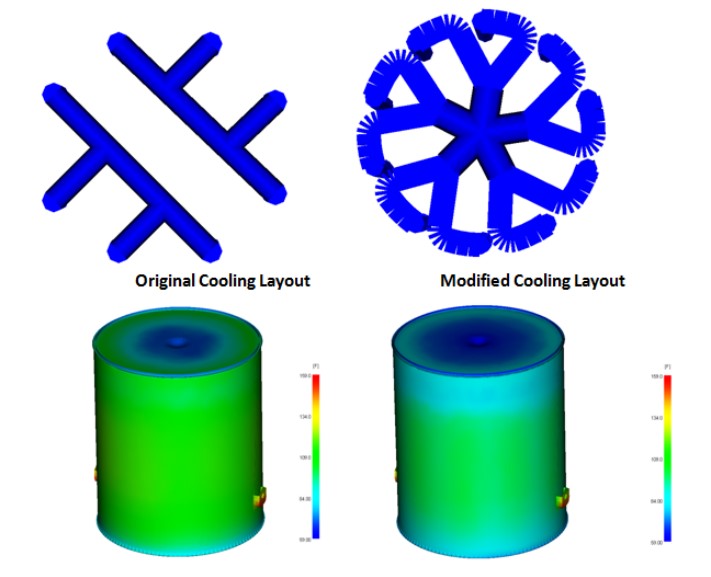
Figure 3: By modifying the cooling layout in the core cap the mold temperature within the core was reduced.
For further information regarding injection molding and mold design, check out Simulate Your Way to a Better Mold.