Designers and engineers of plastic parts use the injection molding process to produce complex parts that require precise dimensions. After development cost and investment in tooling, expectations are that the first articles will pass inspection and meet the print. However, when critical dimensions are not maintained, a solution has to be found quickly to minimize downtime and cost. Incorporating simulation into the design process can help determine if the part can be manufactured within tolerance, and can be a quick and effective way of determining what is causing the warpage of the part so a solution can be found.
Why do plastics warp?
While being injected into the mold, the molten plastic shrinks as it cool. Ideally, the plastic would shrink uniformly in all directions and the mold designer could simply scale the part, and it would shrink to the correct dimensions. However, plastics exhibit anisotropic (non-uniform) shrinkage, which leads to development of residual stresses. Once the part is ejected from the mold, these stresses need to be relieved, which causes the part to distort and warp. It is this non-uniform shrinkage of the plastic that is driving the parts to warp.
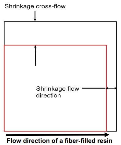
Figure 1: Molten plastic exhibits
anisotropic (non-uniform) shrinkage
because of how the molecules or fibers
orient during the mold filling process.
There are three main factors that affect the amount of warpage that part will experience:
1) Orientation Effects – This factor refers to how the localized shrinkage of the material varies depending on how the plastic molecules or glass fibers are oriented. The shrinkage rates tend to be different in the flow and cross-flow directions as a result of the molecular elongation during injection, Figure 1. Changing the gate location or adding flow leaders can help alter the mold filling pattern and minimize the effects of orientation on warpage.
2) Area Shrinkage (Differential Shrinkage) – This factor refers to how the shrinkage of the material varies throughout the part (i.e. location relative to the gate). The area shrinkage of the part tends to be higher further from the gate and lower nearer the gate. This factor is typically influenced by the wall thickness distribution of the part and the packing profile used to manufacture the part.
3) Differential Cooling – This factor refers to how the shrinkage rates vary as a result of different cooling rates. When the mold temperatures are different on the two sides of the mold the material in contact with the hot side of the mold cools slower than the material in contact with the cold side of the mold. This tends to create a residual stress profile through the thickness that causes the part to deflect away from the hot mold wall after it has been ejected. Designing the cooling layout to achieve a relatively uniform mold temperature with even cooling rates can help alleviate issues with this factor.
How can simulation help solve warpage issues?
Reviewing the main factors behind warpage shows that they are not necessarily well defined nor easily separated. This makes it difficult to simply look at a part and determine if a part will remain within tolerance, and if it is not what the major cause of the warpage is simply based on experience. Performing an injection molding simulation all the way through a warpage analysis allows the analyst to identify if acceptable parts can be manufactured. The warpage analysis can also break the amount of warpage into the different driving forces, Figure 2. The ability for simulations to separate the warpage into the different factors allows for an acceptable solution to be found more quickly than spending costly trial and error time at the press.
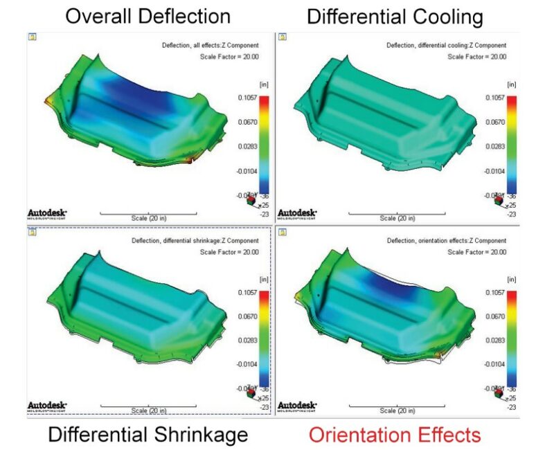
Figure 2: Incorporating a warpage analysis into an injection molding simulation allows the analyst to determine what is driving the warpage and allows a solution to be found quickly.
For further information regarding processing simulation, see Simulate Your Way to a Better Mold.